SCART (Péritel / Euroconnector) 21-pin AV connector: full pinout, RGB/composite/S-Video and audio signals, switching pins and signal levels.
Your support helps keep this website running. Please consider supporting this project. SPONSORDONATE
- Nicola Asuni
Updated:
21 PIN SCART FEMALE at the Video/TV
21 PIN SCART MALE at the Cable
SCART = Syndicat des Constructeurs d’Appareils Radiorécepteurs et Téléviseurs
SCART is a French-originated standard and associated 21-pin connector for connecting audio-visual equipment together. It is also known as Péritel (especially in France) and Euroconnector.
SCART gathers the common analogue audio-visual signals into a single connector: composite video, RGB component video, S-Video (Y/C) and stereo audio, both in and out, plus control and switching lines. Each signal pin is defined as an input or an output, so a straight male-to-male cable automatically connects one device’s outputs to the other’s inputs. It is defined by CENELEC EN 50049-1 and IEC 60933-1, was mandatory on television sets sold in France from 1980, and was the standard AV interconnect in Europe until HDMI displaced it.
Pin
Name
Description
Signal Level
Impedance
1
AOR
Audio Out Right
0.5 V rms
<1k ohm
2
AIR
Audio In Right
0.5 V rms
>10k ohm
3
AOL
Audio Out Left + Mono
0.5 V rms
<1k ohm
4
AGND
Audio Ground
5
B GND
RGB Blue Ground
6
AIL
Audio In Left + Mono
0.5 V rms
>10k ohm
7
B
RGB Blue In
0.7 V
75 ohm
8
SWTCH
Function/status & aspect (slow switch)
0–2 V standby; 6 V = 16:9; 12 V = 4:3
9
G GND
RGB Green Ground
10
CLKOUT
Data 2 / AV.link (EasyLink) control bus
11
G
RGB Green In
0.7 V
75 ohm
12
DATA
Data 1 / AV.link (EasyLink) control bus
13
R GND
RGB Red Ground
14
DATAGND
Data Ground
15
R
RGB Red In / Chrominance
0.7 V (Chrom.: 0.3 V burst)
75 ohm
16
BLNK
Blanking Signal
1-3 V=RGB, 0-0.4 V=Composite
75 ohm
17
VGND
Composite Video Ground
18
BLNKGND
Blanking Signal Ground
19
VOUT
Composite Video Out
1 V
75 ohm
20
VIN
Composite Video In / Luminance
1 V
75 ohm
21
SHIELD
Ground/Shield (Chassis)
Notes
Video Output Level : 1 V p-p +/-2 dB
Video Output Impedance : 75 ohm
Video Frequency Range : 25Hz. - 4.8MHz (+/-1.5 dB)
Video De-emphasis(PAL) : to CCIR 405.1 (625 lines)
Many TV sets have 2 SCART sockets. One is usually uses previous pinout table and the other uses following pinout table. The first can switch from a composite input to RGB input. The second can switch from a composite input to an S-Video input, pin 20 being either composite in or luminance in. Usually the second socket outputs a selectable composite signal on pin 19
Pin
Signal
Level
Impedance
1
Audio Out Right
0.5 V rms
<1k ohm
2
Audio In Right
0.5 V rms
>10k ohm
3
Audio Out Left + Mono
0.5 V rms
<1k ohm
4
Ground Audio
5
RGB Ground Blue
6
Audio In Left + Mono
0.5 V rms
>10k ohm
7
-
-
-
8
Fuction Select
High (9.5-12V) AVmode Low (0-2V) TVmode
>10kohm
9
RGB Ground Green
10
Comms Data 2
11
-
-
-
12
Comms Data 1
13
Ground (chrominance)
14
Ground Data
15
Chrominance input
0.3V
75 ohm
16
-
-
-
17
Ground (luminance)
18
-
-
-
19
Video output (composite)
1V including sync
75 ohm
20
Luminance input
1V including sync
75 ohm
21
Ground/Shield (Chassis)
Signal Levels
Signal
AC level
DC level
Impedance
Red, green, blue
Peak to blanking: 0…0.7 V ±3 dB
0…2 V
75 Ohm
Sync
Peak to peak: 0…0.3 V -3 dB…+10 dB
0…2 V
75 Ohm
Composite video
White to sync: 0…1.0 V ±3 dB
0…2 V
75 Ohm
Chrominance
0…0.3 V -3 dB…+10 dB
0…2 V
75 Ohm
Luminance
0…1.0 V ±3 dB
0…2 V
75 Ohm
MAC
Black to white: 0…1.0 V ±3 dB
0…2 V
75 Ohm
Audio in
0.2…2.0 V (nominal: 0.5 V)
>=10 kOhm
Audio out
Nominal: 0.5 V (maximum: 2.0 V)
<=1 kOhm
Video status
Low data rate communication: 0.0…2.0 V (e.g. remote control; Easylink)
Internal: 0.0…2.0 V External (16:9): 4.5…7.0 V External (4:3): 9.5…12.0 V
In: ZR ≥ 10 kOhm, ZC ≤ 2 nF; Out: ZR ≤ 1 kOhm
RGB status
Internal: 0.0…0.4 V External: 1.0…3.0 V
75 Ohm
Notes
A formal interface description is given in the CENELEC EN 50 049-1:1989 standard or in the IEC 933-1 standard.
SCART S-Video Connection
Output connector
Input connector
1
Audio right out
3
Audio left (or mono) out
4
Audio return
15
Chrominance out
13
Chrominance return
8
Video status out
19
Luminance out
17
Luminance return
21
Shield
SCART Composite Video Connection
Output connector
Input connector
1
Audio right out
3
Audio left (or mono) out
4
Audio return
8
Video status out
19
Composite video out
17
Composite video return
21
Shield
SCART (Composite) Decoder Connection
Receiver connector
Decoder connector
1
Audio right out
2
Audio right in
3
Audio left out
6
Audio left in
4
Audio return
8
Video status in
19
Baseband out (scrambled)
17
Baseband out return
20
Composite video in (unscrambled)
18
Composite video in return
21
Shield
SCART EasyLink Connection (additional)
Television connector
Video recorder connector
10
I/O Control Bus
Notes
EasyLink (AV.link) enables bi-directional communication between a television set and a video recorder over pins 10 and 12. This way a video recorder can, for example, copy the channel settings of the television set, or start playback to wake the TV onto the correct input.
Switching pins. Pin 8 is a slow DC switch that signals source presence and aspect ratio (0–2 V = off/standby, about 6 V = AV active 16:9, about 12 V = AV active 4:3) and can wake a set and auto-select the AV input. Pin 16 is the fast-blanking line that selects RGB (1–3 V) instead of composite (0–0.4 V).
S-Video (Y/C) mode. SCART has no dedicated S-Video pins: pin 15 (normally RGB red) carries chrominance and pin 20 (normally composite-in) carries luminance, which is why a socket cannot do RGB and S-Video at once.

 21 PIN SCART FEMALE at the Video/TV
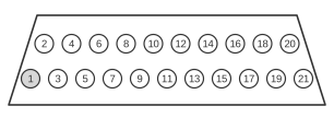 21 PIN SCART MALE at the Cable