
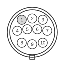
 10 pin mini-din female connector at the device.
The Amino AmiNET 110 is an MPEG-2 IPTV set-top box produced by Amino Communications that outputs analogue video and stereo audio through a single 10-pin mini-DIN socket on the rear panel. Depending on the locale-specific cable supplied (Amino part 502-419 or equivalent), the connector breaks out to composite video, S-Video (Y/C), or SCART, together with stereo audio. The device supports both PAL and NTSC analogue video output, with signal levels conforming to ITU-R BT.1700 (1 V peak-to-peak composite, 75 Ω). A separate RCA socket carries the SP-DIF digital audio output and is not part of this connector.
| Pin | Composite/RGB | S-video | S-video alternative |
|---|---|---|---|
| 1 | Audio Left | Audio Left | Audio Left |
| 2 | RGB status | ||
| 3 | Composite VBS | Luminance | Luminance |
| 4 | Audio GND | Audio GND | Audio GND |
| 5 | Video status | video status | |
| 6 | Red | Chrominance | |
| 7 | Video GND | Video GND | Video GND |
| 8 | Audio Right | Audio Right | Audio Right |
| 9 | Green | Synchro+Luminance | |
| 10 | Blue |
Notes
- RGB Status (pin 2) should be +1…3V for RGB display.
- The 10-pin mini-DIN housing is a non-standard pin-count variant; the IEC 60130-9 family standardises the 9.5 mm outer diameter but not the 10-pin arrangement. The connector is keyed and is not mechanically compatible with standard 4-pin S-Video or 7-pin mini-DIN sockets.
- The interface is proprietary; Amino Communications never published an official pin assignment specification.
- Composite video and audio signal levels conform to ITU-R BT.1700: NTSC 1 V p-p (sync tip −286 mV, peak white +714 mV); PAL 1 V p-p (sync tip −300 mV, peak white +700 mV); source and load impedance 75 Ω.
Signals
- Audio Left — Left-channel analogue stereo audio output; consumer line level, unbalanced.
- RGB status — Voltage present when the box is operating in RGB output mode; approximately +1–3 V, consistent with SCART-compatible RGB-select conventions.
- Composite VBS — Composite video (CVBS) output carrying luminance, colour subcarrier, and sync; 1 V p-p into 75 Ω, PAL or NTSC per device setting.
- Audio GND — Ground return for the left and right audio channels.
- Video status — Signal indicating the active video output mode; exact behaviour is not publicly documented.
- Red — Red (R) component of the analogue RGB output; 75 Ω.
- Video GND — Ground return for all video signals (composite, luminance, chrominance, RGB).
- Audio Right — Right-channel analogue stereo audio output; consumer line level, unbalanced.
- Green — Green (G) component of the analogue RGB output; also used as combined sync-on-luma (Synchro+Luminance) in the S-Video alternative wiring.
- Blue — Blue (B) component of the analogue RGB output; 75 Ω.
- Luminance (Y) — Luminance signal with embedded sync for S-Video (Y/C) output; 1 V p-p, 75 Ω, per the S-Video convention shared with the 4-pin mini-DIN standard (pins 1–4).
- Chrominance (C) — Chrominance subcarrier for S-Video output; approximately 0.3 V p-p, 75 Ω; 4.43 MHz (PAL) or 3.58 MHz (NTSC).