
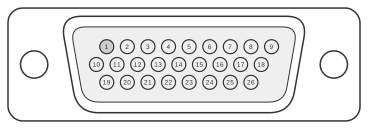
 26 pin hi-density D-SUB female connector at the device.
The ASK Proxima Impression 960 and A6+ were XGA (1024×768) LCD projectors manufactured by ASK A/S between approximately 1995 and 1997. Each model’s SOURCE input port uses a proprietary 26-pin high-density D-SUB female connector that simultaneously carries analogue RGB video signals from the host computer into the projector and passes them back out to an optional local CRT monitor. Synchronisation signals (horizontal, vertical, and composite/vertical) travel through the same connector in both directions, making this a fully multiplexed pass-through interface with no governing industry standard. The connector is accessed via a VGA/XGA V-Split cable (terminating in 15-pin D-SUB plugs) or a BNC V-Split cable for workstations fitted with BNC outputs.
| Pin | Description |
|---|---|
| 1 | Analog R in |
| 2 | Anolog G in |
| 3 | Analog B in |
| 4 | not used |
| 5 | not used |
| 6 | not used |
| 7 | Analog R out |
| 8 | Analog G out |
| 9 | Analog B out |
| 10 | Analog R Gnd in |
| 11 | Analog G Gnd in |
| 12 | Analog B Gnd in |
| 13 | not used |
| 14 | not used |
| 15 | not used |
| 16 | Analog R gnd out |
| 17 | Analog G gnd out |
| 18 | Analog B gnd out |
| 19 | Hsync in |
| 20 | C/Vsync in |
| 21 | Digital gnd |
| 22 | PCID0 |
| 23 | PCID1 |
| 24 | Digital gnd |
| 25 | Hsync out |
| 26 | Vsync out |
Notes
The connector is fitted on the rear panel of the projector and is labelled SOURCE 1, SOURCE 2, or SOURCE 3 depending on the model. The 960 supports up to three SOURCE ports; the A6+ supports two. The high-density 26-pin D-SUB shell is physically similar to the 26-pin HD connector used on some SCSI-2 devices but carries entirely different and proprietary signals — do not confuse the two. Pins 4–6 and 13–15 are explicitly listed as NOT USED in the manufacturer documentation; leaving them unconnected is correct. The MOUSE port on the same projector rear panel is a separate 8-pin miniature DIN female connector and is not documented here.
Signals
- Analog R/G/B in (pins 1–3) — analogue red, green, and blue video input signals from the host computer
- Analog R/G/B out (pins 7–9) — analogue red, green, and blue video output signals looped through to an optional local CRT monitor
- Analog R/G/B Gnd in (pins 10–12) — signal ground returns for the respective RGB input lines
- Analog R/G/B gnd out (pins 16–18) — signal ground returns for the respective RGB output lines
- Hsync in (pin 19) — horizontal synchronisation signal from the computer
- C/Vsync in (pin 20) — composite sync or vertical synchronisation signal from the computer
- Digital gnd (pins 21, 24) — digital ground reference for synchronisation and identification circuits
- PCID0 (pin 22) — projector/computer identification bit 0; used by the V-Split cable accessory to identify the connected source
- PCID1 (pin 23) — projector/computer identification bit 1; paired with PCID0 for source identification
- Hsync out (pin 25) — horizontal synchronisation signal passed through to the local monitor output
- Vsync out (pin 26) — vertical synchronisation signal passed through to the local monitor output