
The GM overhead monitor is a Panasonic-manufactured OEM rear-seat entertainment (RSE) display fitted to a range of General Motors full-size trucks and SUVs — including the Escalade, Tahoe, Yukon, Suburban, Avalanche, Silverado, Sierra, and Hummer H2 — bearing GM part numbers 15948136, 15294214, and 15293772. The unit communicates with the vehicle via SAE J1850 VPW (GM “Class 2”) serial data, a single-wire bus operating at 10.4 kbit/s that was standard on GM platforms from the mid-1990s until it was phased out in favour of CAN bus. Composite (NTSC) analogue video is delivered via a differential pair, alongside analogue audio and several Class 2 control lines, all on a single proprietary 10-pin harness connector. The DVD player itself was integrated into the vehicle’s AM/FM/CD head unit rather than housed in the overhead display.
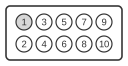
| Pin | Description | Color |
|---|---|---|
| 1 | Video Input + | white |
| 2 | Video Input - | black |
| 3 | NC | |
| 4 | NC | |
| 5 | Dual Control (GM) | green |
| 6 | Ground (-) | black |
| 7 | Batt (+12V) | yellow |
| 8 | Display Enable (+12V) | red |
| 9 | Brightness control (GM) | blue |
| 10 | Mode Control (GM) | orange |
Notes
- For video you need pins 1 and 2, plus power (ground to pin 6 and +12V power to pins 7 and 8). Pin 7 should be constant +12V and pin 8 should be your switched ignition supply (+12V to turn on the display).
- The three “GM” control signals on pins 5, 9, and 10 operate over the SAE J1850 VPW (Class 2) single-wire data bus at 10.4 kbit/s. Signal high is 4.25–20 V; signal low is below 3.5 V.
- When retaining the original overhead monitor with an aftermarket head unit, an interface module such as the PAC GMRVD is required to retain the Class 2 bus communication, the infrared wireless headphone system, and the safety-interlock functions.
- There is no digital video interface on this connector; video is composite (NTSC) analogue only.
Signals
- Video Input + — positive leg of the composite NTSC video differential pair (pin 1, white)
- Video Input - — negative/shield leg of the composite video pair; forms a balanced input with pin 1 (pin 2, black)
- NC — not connected; pins 3 and 4 are unused in known implementations
- Dual Control (GM) — SAE J1850 VPW Class 2 serial data line carrying overhead-display control commands from the vehicle bus (pin 5, green)
- Ground (-) — chassis/signal ground return for power and audio (pin 6, black)
- Batt (+12V) — constant +12 V supply for memory and keep-alive functions (pin 7, yellow)
- Display Enable (+12V) — switched +12 V input; applying voltage here powers on and enables the display panel (pin 8, red)
- Brightness control (GM) — Class 2 bus signal used to adjust display backlight brightness (pin 9, blue)
- Mode Control (GM) — Class 2 bus signal used to switch the display between operating modes (e.g., video/DVD) (pin 10, orange)