
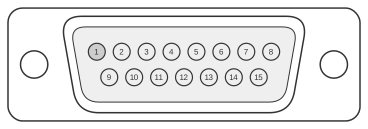
 DB15M - 15 pin male connector
The Panasonic VTR DB-15 connector is a 15-pin D-subminiature male interface found on Panasonic consumer video tape recorders of the early 1980s, such as the NV-8950, providing a dedicated editing and accessory port. It carries composite video, chroma, hue, setup level, and horizontal phase reference signals alongside ±12 V DC power rails, enabling connection to compatible editing controllers and accessory decks. The “Sys SC” lines (Crs1, Crs2, Fine) are sub-carrier synchronisation signals used to lock the VTR’s colour reference to an external source or editing system. Three pins remain unconfirmed in available documentation; the pin table below reflects the best information from secondary community sources, as no freely available primary Panasonic service manual with a complete pin assignment list has been located.
| Pin | Description |
|---|---|
| 1 | ? |
| 2 | Setup |
| 3 | Chroma |
| 4 | GND |
| 5 | +12VDC |
| 6 | Sys H Phase |
| 7 | Sys SC Crs1 |
| 8 | -12VDC |
| 9 | Hue |
| 10 | Video |
| 11 | GND |
| 12 | ? |
| 13 | ? |
| 14 | Sys SC Fine |
| 15 | Sys SC Crs2 |
Notes
- The connector shell is a standard DB-15 (DE-15) D-sub male housing; the mating cable uses a DB-15 female plug.
- Pins 1, 12, and 13 are unconfirmed; their functions have not been verified against a primary Panasonic service manual.
- The ±12 V DC rails (pins 5 and 8) supply power to an attached editing controller or accessory unit.
- The Sys H Phase and Sys SC (sub-carrier coarse/fine) signals are analogue sync references; shielded cable is recommended for these lines to avoid interference.
- This editing interface is distinct from the RS-422A DE-9 serial control protocol used on professional Sony and Panasonic broadcast VTRs of the same era.
Signals
- ? (pin 1) — function unconfirmed; possibly a control or sync line
- Setup — video setup (pedestal) level signal, used to calibrate black level for the composite video path
- Chroma — colour (chrominance) signal
- GND — signal ground (pins 4 and 11)
- +12VDC — +12 V DC power output to accessory/controller
- Sys H Phase — system horizontal phase reference; aligns horizontal timing of an attached device to the VTR
- Sys SC Crs1 — system sub-carrier coarse synchronisation, first line; part of the colour reference lock mechanism
- -12VDC — −12 V DC power output to accessory/controller
- Hue — hue (colour phase) control signal
- Video — composite video signal
- ? (pin 12) — function unconfirmed
- ? (pin 13) — function unconfirmed
- Sys SC Fine — system sub-carrier fine synchronisation; provides precise sub-carrier phase alignment
- Sys SC Crs2 — system sub-carrier coarse synchronisation, second line
References
- Panasonic NV-8950 User Manual (Panasonic / Matsushita Electric, c. 1982) — archived at archive.org/details/PanasonicNV8950Manual