
MIDI = Musical Instrument Digital Interface
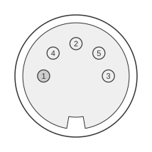 5 PIN DIN 180° (DIN41524) FEMALE at the peripheral.
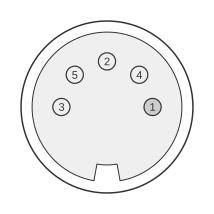 5 PIN DIN 180° (DIN41524) MALE at the cable.
MIDI (Musical Instrument Digital Interface) connects electronic musical instruments over a 31.25 kbaud asynchronous serial current loop on a 5-pin 180° DIN connector. Only pins 4 and 5 carry the signal; pins 1 and 3 are unused. At a MIDI IN, pins 4 and 5 feed an opto-isolator, so there is no direct electrical connection to the sending device — this galvanic isolation prevents ground loops and hum, which is why pin 2 (the cable shield) is left unconnected at the input.
| Pin | Name | Description |
|---|---|---|
| 1 | n/c | Not connected |
| 2 | n/c | Not connected |
| 3 | n/c | Not connected |
| 4 | CSRC | Current Source |
| 5 | CSINK | Current Sink |
Notes
- MIDI is a 5 mA current loop carried on pins 4 and 5 (a logical 0 is current on). The framing is 31.25 kbaud (±1%), 8 data bits, no parity, 1 stop bit (8-N-1), sent LSB first.
- At a MIDI IN the loop drives the LED of an opto-isolator (such as a 6N138 or PC-900), so the receiver shares no electrical ground with the transmitter.
- Pin 2 (the cable shield) is grounded only at the MIDI OUT/THRU end; at the IN it has no DC path to ground, which prevents a ground loop between the two devices.
- Pins 1 and 3 are unused.
Signals
- CSRC (current source, pin 4) — one side of the current loop, feeding the opto-isolator LED.
- CSINK (current sink, pin 5) — the return side of the loop.
- Pin 2 — cable shield; not connected at a MIDI IN (grounded only at the OUT/THRU end).
- Pins 1, 3 — not used.
References
- MMA — 5-pin DIN electrical specs (MIDI 1.0 Electrical Specification) — the official MIDI hardware interface.