
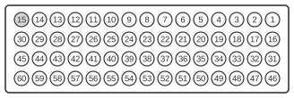
The SGI IndyCam digital video port is a proprietary high-density 60-pin connector fitted to the SGI Indy workstation, introduced in 1993. It connects the IndyCam camera — co-developed by Silicon Graphics and Teleview Research — to the VINO (Video Input, No Output) subsystem on the Indy motherboard, supporting NTSC 640×480 and PAL 768×576 digital capture. The interface protocol is explicitly described in SGI documentation as similar to, but not exactly the same as, the CCIR 601 parallel digital component standard. The full 60-pin interface carries two digital video channels (one input-only and one bidirectional), though the IndyCam connector exposes only the input-only channel; the remaining pins are reserved.
| Pin | Name |
|---|---|
| 1 | (Reserved) |
| 2 | (Reserved) |
| 3 | (Reserved) |
| 4 | (Reserved) |
| 5 | (Reserved) |
| 6 | (Reserved) |
| 7 | SERIAL CONTROL DATA |
| 8 | (Reserved) |
| 9 | SERIAL CONTROL CLOCK |
| 10 | (Reserved) |
| 11 | (Reserved) |
| 12 | CLOCK GROUND |
| 13 | CLOCK |
| 14 | (Reserved) |
| 15 | (Reserved) |
| 16 | (Reserved) |
| 17 | (Reserved) |
| 18 | (Reserved) |
| 19 | (Reserved) |
| 20 | (Reserved) |
| 21 | (Reserved) |
| 22 | +12 |
| 23 | +5 |
| 24 | -12 |
| 25 | (Reserved) |
| 26 | (Reserved) |
| 27 | DATA(7) GROUND |
| 28 | DATA(7) |
| 29 | DATA(6) GROUND |
| 30 | DATA(6) |
| 31 | DATA(3) |
| 32 | DATA(3) GROUND |
| 33 | DATA(4) |
| 34 | DATA(4) GROUND |
| 35 | DATA(5) |
| 36 | DATA(5) GROUND |
| 37 | (Reserved) |
| 38 | (Reserved) |
| 39 | (Reserved) |
| 40 | (Reserved) |
| 41 | (Reserved) |
| 42 | (Reserved) |
| 43 | (Reserved) |
| 44 | (Reserved) |
| 45 | (Reserved) |
| 46 | DATA(0) |
| 47 | DATA(0) GROUND |
| 48 | DATA(1) |
| 49 | DATA(1) GROUND |
| 50 | DATA(2) |
| 51 | DATA(2) GROUND |
| 52 | (Reserved) |
| 53 | (Reserved) |
| 54 | (Reserved) |
| 55 | (Reserved) |
| 56 | (Reserved) |
| 57 | (Reserved) |
| 58 | (Reserved) |
| 59 | (Reserved) |
| 60 | (Reserved) |
Notes
- The connector is a proprietary high-density format, distinct from standard D-Sub shells. It is not mechanically or electrically compatible with any standard consumer video connector.
- The interface protocol is similar to CCIR 601 parallel digital video but is not identical; the full specification was detailed in an internal SGI Digital Video Specification document.
- The full connector interface includes a bidirectional data channel (DATA(0)–DATA(7) on the XDATAIO bus) and an input-only channel (XDATAIN bus). The IndyCam camera uses only the input-only channel; the bidirectional channel pins appear as Reserved on the IndyCam-facing connector.
- Power rails (+12 V on pin 22, +5 V on pin 23, –12 V on pin 24) supply the camera directly from the workstation.
- Serial camera control (I²C-style) is carried on pin 7 (SERIAL CONTROL DATA) and pin 9 (SERIAL CONTROL CLOCK), with pin 12 providing the dedicated clock ground return.
Signals
- SERIAL CONTROL DATA — serial bidirectional control data line for camera configuration (pin 7)
- SERIAL CONTROL CLOCK — serial clock for camera control communications (pin 9)
- CLOCK GROUND — dedicated ground return for the pixel clock line (pin 12)
- CLOCK — pixel clock input from the IndyCam camera (pin 13)
- +12 — +12 V DC power supply to the camera (pin 22)
- +5 — +5 V DC power supply to the camera (pin 23)
- -12 — –12 V DC power supply to the camera (pin 24)
- DATA(7)–DATA(0) — 8-bit parallel digital video data bus (input-only channel); each data line is paired with a dedicated differential ground return (e.g. DATA(7) GROUND on pin 27, DATA(7) on pin 28)
- (Reserved) — pins not connected to the IndyCam camera; correspond to the bidirectional XDATAIO channel and ancillary signals (TRIGOUT, SDA_SEND, SCL_SEND, spare lines) present in the full SGI Digital Video Interface but not exposed on this connector