
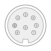
 8 PIN DIN (DIN45326) FEMALE at the Computer
The Commodore C16, C116, and Plus/4 are members of the 264 series and share a common external audio/video connector (CN7) — an 8-pin DIN socket (Commodore part 325573-01) mounted on the rear of the computer. Although the connector is physically identical to the 8-pin DIN used on the later C64 and C128, the pin assignments are entirely different and the two are not interchangeable. The connector carries composite video output, separate synchronisation and luminance signals, colour (chroma) signals, audio input and output, and a +5 V supply rail, the last being used to power the external RF modulator. Both the C16 and Plus/4 service manuals (October 1984) document this architecture.
| Pin | Name | Dir | Description |
|---|---|---|---|
| 1 | LUM | OUT | Luminance (monochrome video) |
| 2 | GND | - | Ground |
| 3 | AOUT | OUT | Audio out |
| 4 | VOUT | OUT | Composite Video out |
| 5 | AIN | IN | Audio in (into the SID chip) |
| 6 | COLOR | - | Color ? |
| 7 | n/c | - | Not connected |
| 8 | +5VDC | OUT | +5 VDC |
Notes
- Direction is Computer relative Monitor.
- The 8-pin DIN connector (DIN45326) is keyed; it cannot be inserted in the wrong orientation, but the 264-series pinout is incompatible with the C64/C128 8-pin DIN — using a C64 cable on a 264-series machine will not produce a correct picture.
- The Plus/4 service manual (PN-314001-04) designates the connector CN7 and lists Commodore part number 325573-01.
- The C16 service manual (PN-314001-03) documents an internal 6-pin DIN (CN6, part C 325573-01) that connects the mainboard to the built-in RF modulator; the external A/V port architecture is shared across the 264 series.
Signals
- LUM — Sync and luminance output; carries the combined synchronisation and brightness signal for use with compatible monitors or a Y/C-capable display.
- GND — Signal ground reference.
- AOUT — Audio output from the computer to an external monitor or amplifier.
- VOUT — Composite video output (luminance, chrominance, and sync combined on a single line).
- AIN — Audio input into the computer; purpose not publicly documented beyond the service manual label.
- COLOR — Colour (chroma) signal; direction not specified in the page’s source data.
- n/c — Not connected.
- +5VDC — +5 V DC supply output, used to power the external RF modulator unit.