
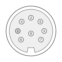
 8 PIN DIN “C” FEMALE at the computer
The Commodore Amiga 1000, released in 1985, features an 8-pin DIN connector on its rear panel that carries composite video, stereo audio, and +12 V power for an external RF modulator such as the Commodore A520. This connector is unique to the A1000; later Amiga models — the A500, A2000, and A3000 — replaced it with a DB-23 video port. Two pins (1 and 6) are left unconnected, whilst pins 2 and 5 both provide ground returns.
| Pin | Name | Dir | Description |
|---|---|---|---|
| 1 | n/c | - | Not connected |
| 2 | GND | - | Ground |
| 3 | AUDL | OUT | Audio Left |
| 4 | CVIDEO | OUT | Composite Video |
| 5 | GND | - | Ground |
| 6 | n/c | - | Not connected |
| 7 | +12V | OUT | +12 VDC |
| 8 | AUDR | OUT | Audio Right |
Signals
- n/c — pins 1 and 6 are not connected
- GND — signal ground (pins 2 and 5)
- AUDL — analogue stereo audio left channel output
- CVIDEO — NTSC/PAL composite video output
- +12V — +12 VDC supply to power an external RF modulator
- AUDR — analogue stereo audio right channel output
Notes
- Direction is computer relative to monitor/modulator.
- The +12 V on pin 7 is intended to power an external RF modulator (e.g. Commodore A520); it is absent on A500/A2000/A3000 which use the DB-23 video connector instead.
- The Amiga 1000 outputs four custom hardware audio channels mixed to stereo left and right outputs on this connector.