
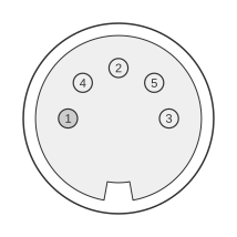
 5 PIN DIN 180° (DIN41524) FEMALE at the Computer.
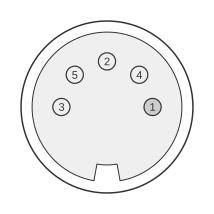 5 PIN DIN 180° (DIN41524) MALE at the Cable.
The Commodore 64 uses a proprietary DIN connector for combined audio and video output, with two distinct variants across its production run. Early C64 boards (PCB 326298-01, Commodore part 903362-01) carry a 5-pin DIN that provides composite video only on pin 4; the VIC-II chroma signal is not brought out. Later C64 and C64C boards (PCB 250407-04 and 250425-01, Commodore part 325573-01) moved to an 8-pin DIN that additionally exposes separate luminance and chroma outputs, enabling higher-quality S-Video-like display when used with compatible monitors such as the Commodore 1702 or 1902A. Both variants are documented in the Commodore 64 Service Manual (PN-314001-02, September 1985).
| Pin | Name | Dir | Description |
|---|---|---|---|
| 1 | LUM | OUT | Luminance |
| 2 | GND | —— | Ground |
| 3 | AOUT | OUT | Audio Out |
| 4 | VOUT | OUT | Video Out |
| 5 | AIN | IN | Audio In |
Notes
- Direction is Computer relative Monitor.
- The early C64 5-pin DIN connector (part 903362-01) provides composite video on pin 4 only; luminance and chroma are not separately available.
- The later C64 and C64C 8-pin DIN connector (part 325573-01) exposes separate luma/sync and chroma outputs alongside composite video and audio in/out; pins 7 and 8 are not connected.
- The Commodore 1702 monitor accepts both cable types: a 3-RCA cable (audio/luma/chroma) from the 8-pin DIN, or a 2-RCA cable (composite+audio) from a 5-pin DIN, selected via a rear-panel switch.
- The luma/chroma output is labelled “Separated LCA” in Commodore 1902A monitor documentation and is similar in signal level to S-Video (1 Vp-p, 75 Ω) but uses a different connector and pinout; it is not formally compliant with the EIAJ RC-5237 S-Video standard.
Signals
- LUM — Luminance and sync output from the VIC-II chip (1 Vp-p, 75 Ω); available on the later 8-pin DIN only.
- GND — Signal ground.
- AOUT — Audio output.
- VOUT — Composite video output (luminance and colour mixed internally); also fed to the RF modulator.
- AIN — Audio input.