
The Commodore 128 and C64C use an 8-pin DIN (DIN45326) monitor connector (CN5, Commodore part 325573-01) to carry combined audio and video output. Later C64 boards and the C64C replaced the earlier 5-pin DIN with this 8-pin version, which adds separate luminance and chroma outputs alongside composite video and bidirectional audio. The C128 service manual (PN-314001-08, November 1987) specifies video signal levels of 1 Vp-p at 75 Ω with a 0.5 V DC offset, and audio output at 1 Vp-p into 1 kΩ. The C128 additionally provides a separate 80-column RGBI output via the 8563 VDC chip, which is carried on a distinct connector and is not part of this port.
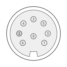 8 PIN DIN (DIN45326) FEMALE at the Computer
| Pin | Name | Dir | Description |
|---|---|---|---|
| 1 | LUM | OUT | Luminance (monochrome video) |
| 2 | GND | - | Ground |
| 3 | AOUT | OUT | Audio out |
| 4 | VOUT | OUT | Composite Video out |
| 5 | AIN | IN | Audio in (into the SID chip) |
| 6 | n/c | - | Not connected |
| 7 | n/c | - | Not connected |
| 8 | C | OUT | Chroma |
Notes
- Direction is Computer relative Monitor.
- The connector is an 8-pin DIN (DIN45326), female on the computer side; monitor cables use a male DIN plug at the computer end and typically terminate in RCA plugs at the monitor.
- Signal levels: luminance/sync, chroma, and composite video are all 1 Vp-p at 75 Ω with a 0.5 V DC offset; audio output is 1 Vp-p at 1 kΩ impedance.
- The VIC-IIe luma/sync signal originates on VIC-II pin 15 and chroma on pin 14; these are routed directly to the monitor connector.
- The separate luminance and chroma outputs provide S-Video-like quality; Commodore’s own documentation for the 1902A monitor refers to this signal pair as “Separated LCA” rather than S-Video, and the connector/pinout does not conform to the later EIAJ RC-5237 S-Video standard.
- The C128’s VIC video interface is noted in the service manual as “very similar to the output of the 8-pin video C64 units”, confirming backward compatibility with C64C monitor cables.
- The Commodore 264-series 8-pin DIN (used on the C16, C116, and Plus/4) uses the same physical connector part (325573-01) but a completely different pin assignment and is not electrically compatible with this port.
Signals
- LUM — Luminance and sync output (Y signal); 1 Vp-p, 75 Ω, 0.5 V DC offset.
- GND — Signal ground.
- AOUT — Audio output from the SID chip; 1 Vp-p at 1 kΩ impedance.
- VOUT — Composite video output (CVBS), combining sync, luminance, and colour; 1 Vp-p, 75 Ω, 0.5 V DC offset. Also fed to the internal RF modulator.
- AIN — Audio input routed into the SID chip’s external audio input.
- n/c — Not connected (pins 6 and 7).
- C — Chroma output; 1 Vp-p, 75 Ω, 0.5 V DC offset.