
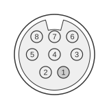
 Minidin 8 Pin Female (On the ATI video card)
ATI All-In-Wonder cards from the late 1990s and 2000s featured a proprietary 8-pin Mini-DIN connector on the card bracket for external audio and video input. The connector carries composite video (CVBS), S-Video luminance and chrominance (Y/C), and stereo audio on a single cable, allowing connection to VCRs, camcorders, and other AV sources via an appropriate breakout cable. ATI’s All-In-Wonder series integrated a TV tuner and video capture engine — based on the ATI Rage Theater video decoder in later models — directly onto the graphics card. The connector pinout is proprietary to ATI and is not shared with any open industry standard.
| Signal | ATI connector |
|---|---|
| Composite Video Signal (I/O) | 1 |
| Composite Video Ground | 2 |
| Audio Ground | 3 |
| Audio Right Signal (I/O) | 4 |
| Ground | 5 |
| Color (Chrominance) (I/O) | 6 |
| Audio Left Signal (I/O) | 7 |
| Intensity (Luminance) (I/O) | 8 |
| Shield | Ground |
Signals
- Composite Video Signal — analogue composite video input/output (CVBS) on pin 1.
- Composite Video Ground — dedicated return ground for the composite video signal on pin 2.
- Audio Ground — shared audio return ground for both stereo channels on pin 3.
- Audio Right Signal — right-channel line-level stereo audio input/output on pin 4.
- Ground — additional signal ground on pin 5.
- Color (Chrominance) — S-Video chrominance (C) component on pin 6, used when operating in S-Video mode.
- Audio Left Signal — left-channel line-level stereo audio input/output on pin 7.
- Intensity (Luminance) — S-Video luminance (Y) component on pin 8, also carries composite sync in S-Video mode.
- Shield — connector shell ground, tied to chassis ground.
Notes
The connector is physically identical to an 8-pin Mini-DIN (large DIN-8) but uses a proprietary ATI-defined pinout; it is not compatible with standard PS/2, serial, or other common 8-pin Mini-DIN devices. An ATI-specific breakout cable is required to route signals to individual RCA or 3.5 mm jacks. Pins 1 and 8 share the same conductor when operating in composite-only mode; S-Video mode uses pins 6 and 8 for the C and Y signals respectively. The shield connects to video ground and should be treated as a chassis reference.