
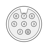
 8 pin mini-DIN female connector at the computer.
The Intel/IBM ActionMedia II Delivery Board provides an 8-pin Mini-DIN female receptacle (FRU 69F9736) for audio and video capture, driven by the Intel i750 (82750PB/DB) DVI video processor chipset. The connector accepts composite, S-VHS (Y/C), RGB, RGBS, and SCART signals depending on which breakout adapter is attached, alongside stereo line-level audio. The product was jointly developed by Intel and IBM in the early 1990s as part of the DVI (Digital Video Interactive) multimedia expansion card line for ISA and Micro Channel bus systems.
| Pin | Description |
|---|---|
| 1 | Composite Sync Input |
| 2 | Blue Video Input |
| 3 | Red Video Input |
| 4 | Video Ground |
| 5 | Left Audio Input |
| 6 | Green Video Input |
| 7 | Right Audio Input |
| 8 | Audio Ground |
Table below shows usage of inputs depending of the type:
| Mode | 3 (R) | 6 (G) | 2 (B) | 1 (S) |
|---|---|---|---|---|
| Composite video 1 (VCR) | Yes | |||
| Composite video 2 | Yes | |||
| SVHS (Y/C) | Y | C | ||
| RGB (sync-on-green) | R | G | B | |
| RGBS | R | G | B | S |
Signals
- Composite Sync Input (pin 1) — horizontal/vertical composite sync signal; used in RGBS mode and identifies the Yellow wire on the Audio/Video Capture Cable
- Blue Video Input (pin 2) — blue channel for RGB/RGBS input modes
- Red Video Input (pin 3) — red channel for RGB/RGBS modes; also carries composite video signal in composite mode 1 (VCR)
- Video Ground (pin 4) — common ground reference for all video signal pins
- Left Audio Input (pin 5) — left-channel stereo line-level audio input
- Green Video Input (pin 6) — green channel for RGB/RGBS modes; carries composite video in composite mode 2; carries chroma (C) in S-VHS mode
- Right Audio Input (pin 7) — right-channel stereo line-level audio input
- Audio Ground (pin 8) — common ground reference for audio signal pins
Notes
- The connector is an 8-pin Mini-DIN female receptacle on the ActionMedia II Delivery Board; the mating cable (FRU 69F9736) uses a Male Mini-DIN-8 plug.
- Cable wire colours on the male plug: pin 1 Yellow (Sync), pin 2 Blue, pin 3 Red/Composite, pin 4 Video GND, pin 5 Black (Audio Left), pin 6 Green, pin 7 White (Audio Right), pin 8 Audio GND.
- The video input mode is selected by the breakout adapter attached to the cable; no mode-switching is required at the connector itself.
- The Capture Module daughter board (FRU 69F9735/69F9734) is an optional add-on to the Delivery Board (FRU 69F9733/69F9732); the 8-pin capture connector is part of that module.
- In S-VHS (Y/C) mode pin 3 carries luma (Y) and pin 6 carries chroma (C); pins 2 and 1 are unused.
References
- ActionMedia II — Ardent Tool of Capitalism (compiled from Intel documentation 468478-001 through 468481-002)