
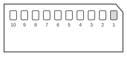
 Memory Stick - Memory Stick Pro - 10 pin connector
The Memory Stick is a proprietary removable flash memory card format introduced by Sony in October 1998, using a 10-pin flat connector and a serial Transfer Protocol Command (TPC) bus. The Memory Stick PRO variant, launched in 2003, retains the same 10-pin connector and pinout but adds a 4-bit parallel interface mode and raises the maximum clock from 20 MHz to 40 MHz, substantially increasing throughput. Both variants operate at 2.7–3.6 V (nominal 3.3 V) and employ 16-bit CRC protection on all transactions. The format was widely used in Sony digital cameras, camcorders, and portable audio players.
| Pin | Signal | Direction | Description |
|---|---|---|---|
| 1 | VSS | ||
| 2 | BS | IN | Bus State. Indicates the Bus State (0-3) on the SDIO and the timing to start signal transfer. |
| 3 | DATA1 | IN/OUT | Data |
| 4 | SDIO/DATA0 | IN/OUT | Serial Data In-Out / Data. Transfer direction and types of data change depending on the Bus State. |
| 5 | DATA2 | IN/OUT | Data |
| 6 | INS | OUT | |
| 7 | DATA3 | IN/OUT | Data |
| 8 | SCLK | IN | Serial CLocK. A host product outputs signals on BS and SDIO af failing edge and inputs (latches) at rising edge. SCLK is always output during BS1-BS3. |
| 9 | VCC | ||
| 10 | VSS |
Signals
- VSS — Ground; both pin 1 and pin 10 are connected to VSS.
- BS — Bus State; encodes bus states 0–3 on the serial interface, indicating direction and timing for signal transfer on SDIO.
- DATA1 — Parallel data line 1; active in 4-bit parallel mode (Memory Stick PRO).
- SDIO/DATA0 — Serial Data In/Out in 1-bit mode; DATA0 in 4-bit parallel mode. Transfer direction and data type are determined by the Bus State.
- DATA2 — Parallel data line 2; active in 4-bit parallel mode (Memory Stick PRO).
- INS — Card insertion detect; asserted by the card to signal its presence to the host.
- DATA3 — Parallel data line 3; active in 4-bit parallel mode (Memory Stick PRO).
- SCLK — Serial clock; supplied by the host. Data on BS and SDIO is output on the falling edge and latched on the rising edge. Clock is active during bus states BS1–BS3. Maximum 20 MHz in 1-bit serial mode; maximum 40 MHz in 4-bit parallel mode (Memory Stick PRO).
- VCC — Supply voltage, 2.7–3.6 V (nominal 3.3 V).
Notes
- Both pin 1 and pin 10 shall be connected to VSS.
- The maximum payload per TPC transaction is 512 bytes; all transactions are protected by 16-bit CRC (polynomial 0x8005).
- Write protection is not a dedicated pin; it is encoded in the Bus State signalling rather than a separate mechanical switch.
- Memory Stick, Memory Stick Duo, MagicGate, MagicGate Memory Stick, and Memory Stick PRO are registered trademarks or trademarks of Sony Corporation.