
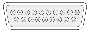
 19 pin D-SUB female connector at the computer.
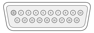 19 pin D-SUB male connector at the cable.
The Macintosh external floppy drive port uses a 19-pin D-subminiature (DB-19) connector, present on every classic Macintosh from the 128K through the IIvi/IIvx and Performa 600. It carries three power rails (−12 V, +5 V, and +12 V), a PWM motor-speed signal unique to the variable-speed Sony 3.5-inch drives, four IWM/SWIM command lines (CA0–CA2 and LSTRB), and serial GCR-encoded read/write data lines. Drive control was handled by the IWM (Integrated Woz Machine) chip in the Mac 128K through the original SE, and by the enhanced SWIM (Super Woz Integrated Machine) from the Mac IIx, SE/30, and Portable onwards.
| Pin | Name | Dir | Description |
|---|---|---|---|
| 1 | CGND | - | Chassis ground |
| 2 | CGND | - | Chassis ground |
| 3 | CGND | - | Chassis ground |
| 4 | CGND | - | Chassis ground |
| 5 | -12V | OUT | -12 VDC |
| 6 | +5V | OUT | +5 VDC |
| 7 | +12V | OUT | +12 VDC |
| 8 | +12V | OUT | +12 VDC |
| 9 | n/c | - | Not connected |
| 10 | PWM | ? | Regulates speed of the drive |
| 11 | CA0 | ? | Control line to send commands to the drive |
| 12 | CA1 | ? | Control line to send commands to the drive |
| 13 | CA2 | ? | Control line to send commands to the drive |
| 14 | LSTRB | ? | Control line to send commands to the drive |
| 15 | WrReq- | ? | Turns on the ability to write data to the drive |
| 16 | HdSel | ? | Control line to send commands to the drive |
| 17 | Enbl2- | ? | Enables the Rd line (else Rd is tristated) |
| 18 | Rd | IN | Data actually read from the drive |
| 19 | Wr | OUT | Data actually written to the drive |
Notes
- Direction is computer relative to disk drive.
- The DB-19 female socket is on the computer; the male plug is on the drive cable.
- Pins 1–4 carry signal ground; the apple2.org/Ports reference lists them as GND rather than chassis ground, consistent with the signal-level grounding role defined in the Guide to the Macintosh Family Hardware (Table 9-5).
- Pin 9 is not connected on the Macintosh DB-19 port (it carries EXTINT* on the Apple IIc variant of the same connector family).
- The PWM signal on pin 10 provides variable-speed motor control required by Sony 400 KB and 800 KB 3.5-inch auto-eject drives; it is absent from the Apple II DB-19 port.
- Pins 11–14 (CA0, CA1, CA2, LSTRB) are the IWM/SWIM register-access command lines; these are physically the same lines called PH0–PH3 on the Apple II version of the connector, where they drove stepper-motor phases for 5.25-inch drives.
- HDSEL (pin 16) selects between the upper and lower heads on double-sided 3.5-inch drives and is driven by the IWM/SWIM chip.
- ENBL2/ (pin 17, active-low) enables the RD read-data line; RD is tri-stated when ENBL2/ is deasserted, preventing bus contention when two drives are daisy-chained.
- RD (pin 18) and WR (pin 19) carry serial GCR-encoded data; the SWIM chip also supports MFM encoding for SuperDrive (HD) operation.
- The DB-19 external port was superseded by HDI-20 (High Density Interface, 20-pin) on the PowerBook Duo and its MiniDock, which carries the same logical signals in a smaller, higher-density housing.
Signals
- CGND — Ground (pins 1–4); signal ground for all drive logic.
- -12V — −12 VDC power rail for drive electronics.
- +5V — +5 VDC power rail for drive logic.
- +12V — +12 VDC power rail for drive motor (carried on two pins for current capacity).
- n/c — Pin 9; not connected on Macintosh models (used as EXTINT* on the Apple IIc).
- PWM — Pulse-width modulated signal used to regulate the rotational speed of variable-speed Sony 3.5-inch drives; absent on Apple II DB-19 ports.
- CA0 — IWM/SWIM command line 0; one of four register-access lines used to send drive state commands.
- CA1 — IWM/SWIM command line 1.
- CA2 — IWM/SWIM command line 2.
- LSTRB — Latch strobe; the fourth IWM/SWIM command line, used to latch the state of CA0–CA2 into the drive controller.
- WrReq- — Write request (active-low); when asserted, enables the drive to accept write data on the WR line.
- HdSel — Head select; selects upper or lower read/write head on double-sided 3.5-inch drives.
- Enbl2- — Drive 2 enable (active-low); enables the RD read-data line; tri-states RD when deasserted.
- Rd — Serial read data; GCR-encoded bitstream read from the disk surface.
- Wr — Serial write data; GCR-encoded (or MFM for SuperDrive) bitstream written to the disk surface.