
50 PIN EDGE or IDC at the computer
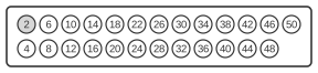
| Pin | Name | Dir | Description |
|---|---|---|---|
| 2 | /REDWC | IN | Reduced Write Current |
| 4 | n/c | - | Reserved |
| 6 | n/c | - | Reserved |
| 8 | n/c | - | Reserved |
| 10 | /FD2S | IN | Disk is two sided |
| 12 | /DCG | IN | Disk has been changed/door open |
| 14 | /SIDE | OUT | Side select |
| 16 | /DLOCK | OUT | Door lock |
| 18 | /HLD | OUT | Head load |
| 20 | /INDEX | IN | Index Pulse |
| 22 | /READY | IN | Ready |
| 24 | n/c | - | Not connected |
| 26 | /SEL1 | OUT | Select Drive 1 |
| 28 | /SEL2 | OUT | Select Drive 2 |
| 30 | /SEL3 | OUT | Select Drive 3 |
| 32 | /SEL4 | OUT | Select Drive 4 |
| 34 | /DIR | OUT | Direction |
| 36 | /STEP | OUT | Step |
| 38 | /WDAT | OUT | Write data |
| 40 | /WGAT | OUT | Write gate |
| 42 | /TR00 | IN | Track 00 (Zero) |
| 44 | /WPROT | IN | Write protect |
| 46 | /RDATA | IN | Read data |
| 48 | n/c | - | Not connected |
| 50 | n/c | - | Not connected |
The 8-inch floppy drive interface originates from the Shugart SA800 and SA801 drives, introduced in 1977, and uses a 50-pin PCB edge-card connector (J1/P1). All odd-numbered pins carry ground, whilst even-numbered pins carry signals using active-LOW, open-collector TTL logic. The SA800 employs an AC induction spindle motor driven via a separate 6-pin AMP Mate-N-Lok power connector (P5/J5) supplying +24 V, +5 V, and −5 V; motor control is therefore not part of the 50-pin signal bus. This interface is a de facto industry standard that preceded the later 34-pin PC floppy bus and served as its direct ancestor.
Notes
- Direction is Computer relative Diskdrive
- All odd pins are GND, Ground
- All signals are active-LOW open-collector TTL; TRUE (asserted) = 0.0–0.4 V sinking up to 40 mA; FALSE (deasserted) = +2.5–+5.25 V open circuit
- Input lines (controller→drive) present 150-ohm impedance; the four multiplexed inputs (/DIR, /STEP, /WDAT, /WGAT) must be terminated with 150-ohm pull-up resistors at the last drive on a multi-drive cable
- /SEL1–/SEL4 (Drive Select) lines are inputs to the drive and activated by the controller; only one drive is selected at a time
- The SA801 variant adds a Sector output (pin 24) for hard-sectored disks; the SA800 leaves pin 24 unconnected
- /HLD (Head Load, pin 18) activates the read/write head solenoid; a minimum settle time is required after assertion before reading or writing
- Maximum recommended cable length is 10 feet, using AMP 1-583717-1 twisted-pair or 3M Scotchflex 3415-0001 flat ribbon cable
- The TG43 (Track Greater Than 43) signal, required on many 8-inch drives to reduce write current beyond track 43, is absent from this connector definition and must be managed separately when adapting 8-inch drives to later controllers
Signals
- /REDWC — Reduced Write Current; asserted by the controller for inner tracks (beyond track 43) on drives that do not support TG43 internally
- /FD2S — Disk Is Two-Sided; drive output indicating a double-sided diskette is loaded
- /DCG — Disk Changed / Door Open; drive output indicating the diskette has been ejected or the door opened since the last drive select
- /SIDE — Side Select; controller output selecting which recording surface (head 0 or head 1) is active on double-sided drives
- /DLOCK — Door Lock; controller output engaging the drive door latch to prevent diskette removal during operation
- /HLD — Head Load; controller output commanding the drive to lower the read/write head onto the diskette surface
- /INDEX — Index Pulse; drive output producing one pulse per disk revolution marking the start of track sector 0
- /READY — Ready; drive output asserted when the drive is selected, the diskette is loaded, and the spindle is at speed
- /SEL1–/SEL4 — Drive Select 1–4; controller outputs selecting one of up to four drives on a shared cable; only one should be asserted at a time
- /DIR — Direction Select; controller output setting the direction of head stepping (low = step inward toward centre)
- /STEP — Step; controller output; each active-LOW pulse moves the head one track in the direction set by /DIR
- /WDAT — Write Data; controller output carrying the flux-transition data stream during write operations
- /WGAT — Write Gate; controller output enabling the write circuitry; must be asserted before write data is valid
- /TR00 — Track 00; drive output asserted when the read/write head is positioned at the outermost track (track 0)
- /WPROT — Write Protect; drive output asserted when the loaded diskette has its write-protect notch covered
- /RDATA — Read Data; drive output carrying the raw flux-transition data stream read from the diskette surface