
ESDI = Enhanced Small Device Interface
Developed by Maxtor in the early 1980’s as an upgrade and improvement to the ST506 design.
Though ESDI and ST506/412 drives share similar looking cables, even to the point of having a twist, the actual data and control signals are very different. One should never mix components from these two drive types. While the ST506/412 interface utilises a standard pulse code to transmit data between the drive and controller, ESDI uses a pulse code that does not require the level to return to zero between pulses. This format is refereed to as NRZ, or Non Return to Zero. By utilising NRZ, the clock that data is transferred by can be increased, there by increasing the throughput to and from the ESDI disk.
 34 PIN IDC MALE at the Controller
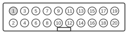 20 PIN IDC MALE at the Controller
 34 PIN IDC FEMALE at the Harddisk
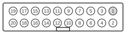 20 PIN IDC FEMALE at the Harddisk
Control connector
| Pin | Name |
|---|---|
| 2 | Head Sel 3 |
| 4 | Head Sel 2 |
| 6 | Write Gate |
| 8 | Config/Stat Data |
| 10 | Transfer Acknowledge |
| 12 | Attention |
| 14 | Head Sel 0 |
| 16 | Sect/Add MK Found |
| 18 | Head Sel 1 |
| 20 | Index |
| 22 | Ready |
| 24 | Transfer Request |
| 26 | Drive Sel 1 |
| 28 | Drive Sel 2 |
| 30 | Drive Sel 3 |
| 32 | Read Gate |
| 34 | Command Data |
Note: All odd are GND, Ground.
Data connector
| Pin | Name |
|---|---|
| 1 | Drive Selected |
| 2 | Sect/Add MK Found |
| 3 | Seek Complete |
| 4 | Address Mark Enable |
| 5 | (reserved, for step mode) |
| 6 | GND |
| 7 | Write Clock+ |
| 8 | Write Clock- |
| 9 | Cartridge Changed |
| 10 | Read Ref Clock+ |
| 11 | Read Ref Clock- |
| 12 | GND |
| 13 | NRZ Write Data+ |
| 14 | NRZ Write Data- |
| 15 | GND |
| 16 | GND |
| 17 | NRZ Read Data+ |
| 18 | NRZ Read Data- |
| 19 | GND |
| 20 | GND |