
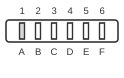
6 PIN MALE EDGE at the computer.
The Commodore VIC-20 and C64 share a proprietary PCB edge connector for cassette tape storage, used with Commodore’s Datassette units (models C2N and 1530). The connector carries six signals — ground, 5 V supply, motor control, serial read, serial write, and a sense line — allowing the computer to stream audio-frequency FSK data to and from standard magnetic tape. Introduced in the early 1980s, the interface was a central storage medium for the VIC-20 and C64 before disk drives became widespread. The SX-64 portable does not include this cassette port.
| Pin | Name | Dir | Description |
|---|---|---|---|
| A-1 | GND | - | Ground |
| B-2 | +5V | OUT | +5 Volts DC |
| C-3 | MOTOR | OUT | Cassette Motor |
| D-4 | READ | IN | Cassette Read |
| E-5 | WRITE | OUT | Cassette Write |
| F-6 | SENSE | OUT | Cassette Sense |
Notes
- Direction is relative to the computer.
- The connector has 12 physical contacts (6 on each side of the PCB edge); each letter–number pair (e.g. A and 1) is shorted together, yielding 6 effective signals. The pitch is 0.156 in (3.96 mm).
- The MOTOR line does not supply TTL logic levels. It delivers approximately 6 V unregulated, derived from the 9 V rail via a transistor switch with a 7.5 V zener clamp, to control the Datassette’s capstan motor relay.
- The Datassette C2N and 1530 both use this 6-pin edge connector. The later Commodore 1531 Datassette, designed for the C16/C116/Plus-4, uses an incompatible 7-pin mini-DIN connector and must not be substituted.
- CASSETTE SENSE detects when the play button on the Datassette is depressed; the computer polls this line before initiating a load or save operation.
- CASSETTE READ connects via a 3.3 kΩ pull-up resistor to the /FLAG input of CIA #1 in the C64.
- The VIC-20 and C64 use the same pinout; both the VIC-20 Programmer’s Reference Guide (Appendix J) and the C64 Programmer’s Reference Guide (Appendix J) document identical assignments.
Signals
- GND — Signal and chassis ground reference; both sides of the edge connector (A and 1) are connected together.
- +5V — Regulated 5 V DC supply sourced from the computer to power the Datassette’s logic circuits.
- MOTOR — Motor control output; the computer switches this line to start and stop the Datassette’s capstan motor, keeping tape movement synchronised with data transfer. Voltage is approximately 6 V unregulated (not TTL).
- READ — Serial data input; analogue FSK audio from the Datassette playback head is conditioned and presented to the computer on this line for software decoding.
- WRITE — Serial data output; the computer drives this line with FSK-encoded audio to record data onto the cassette via the Datassette’s record head.
- SENSE — Play-button sense input; asserted when the Datassette’s play (or record) button is held down, signalling to the computer that a tape operation can proceed.