[Some of the following article parts are reproduces the Wikipedia article “Serial ATA”] In computer hardware, Serial ATA (SATA, is a computer bus technology primarily designed for transfer of data to and from a hard disk. It is the successor to the legacy Advanced Technology Attachment standard (ATA, also known as IDE). This older technology was retroactively renamed Parallel ATA (PATA) to distinguish it from Serial ATA.
The Serial ATA [SATA] bus is defined over two separate connectors, one connector for the data lines and one for the power lines. A Serial ATA Hard drive may also have a third connector for legacy PATA power connections. The PATA power connector may be used in instead of the SATA power to supply a connection which is more rugged and reliable than the SATA-1 power connection.
 SATA connectors (data + power).
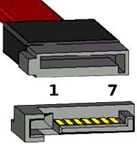 7 pin SATA data
connector.
7 pin SATA data
connector.
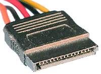
 15 pin SATA Power connector.
 15 pin SATA Power
connector.
15 pin SATA Power
connector.
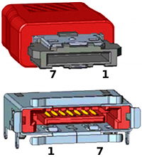 7 pin eSATA data
connector (male + female).
7 pin eSATA data
connector (male + female).
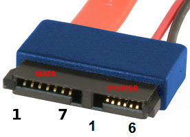 7 pin SATA
slimline connector (data + power(The first pin of power in
center)).
7 pin SATA
slimline connector (data + power(The first pin of power in
center)).
[[/Image:1|image of 7 pin SATA with microSATA power connector]] 7 pin SATA with microSATA power connector (yes, there are adapters, search for “microSATA to SATA”)
The Serial ATA interface [SATA] is the serial version of the IDE [ATA] spec. SATA uses a 4 conductor cable with two differential pairs [Tx/Rx], plus an additional 3 grounds pins and a separate power connector. Data runs at 150MBps [1.5GHz] using 8B/10B encoding and 250mV signal swings, with a maximum bus length of 1 meter. SATA enhancements move the data transfer speed to; 300MBps [3.0Gbps], and then 600MBps [6.0Gbps]. The current speed for SATA is 300Mbps [3Gbps]. Shielded external SATA [eSATA] data cable runs out to a maximum of between 3 feet and 6 feet. eSATA cables are used external to the chassis or case.
SATA Data pinout
| Pin # | Signal Name | Signal Description |
| 1 | GND | Ground |
| 2 | A+ | Transmit + |
| 3 | A- | Transmit - |
| 4 | GND | Ground |
| 5 | B- | Receive - |
| 6 | B+ | Receive + |
| 7 | GND | Ground |
SATA Power pinout
| Pin # | Signal Name | Signal Description |
| 1 | V33 | 3.3v Power |
| 2 | V33 | 3.3v Power |
| 3 | V33 | 3.3v Power, Pre-charge, 2nd mate |
| 4 | Ground | 1st Mate |
| 5 | Ground | 2nd Mate |
| 6 | Ground | 3rd Mate |
| 7 | V5 | 5v Power, pre-charge, 2nd mate |
| 8 | V5 | 5v Power |
| 9 | V5 | 5v Power |
| 10 | Ground | 2nd Mate |
| 11 | Reserved | - |
| 12 | Ground | 1st Mate |
| 13 | V12 | 12v Power, Pre-charge, 2nd mate |
| 14 | V12 | 12v Power |
| 15 | V12 | 12v Power |
Power connector part numbers
- Cable connector: Molex 67582-0000
- Terminals: Molex 67581-0000
- Maximum current per circuit: 1.5 amps
Power supply
The SATA standard specifies a different power connector than the decades-old four-pin Molex connector found on pre-SATA devices. Like the data cable, it is wafer-based, but its wider 15-pin shape prevents accidental mis-identification and forced insertion of the wrong connector type. Native SATA devices favor the SATA power-connector, although some early SATA drives retained older 4-pin Molex in addition to the SATA power connector.
SATA features more pins than the traditional connector for several reasons:
- A third voltage is supplied, 3.3 V, in addition to the traditional 5 V and 12 V.
- Each voltage transmits through three pins ganged together, because the small contacts by themselves cannot supply sufficient current for some devices. (Each pin should be able to provide 1.5 A.)
- Five pins ganged together provide ground.
- For each of the three voltages, one of the three pins serves for hotplugging. The ground pins and power pins 3, 7, and 13 are longer on the plug (located on the SATA device) so they will connect first. A special hot-plug receptacle (on the cable or a backplane) can connect ground pins 4 and 12 first.
- Pin 11 can function for staggered spinup, activity indication, or nothing. Staggered spinup is used to prevent many drives from spinning up simultaneously, as this may draw too much power. Activity is an indication of whether the drive is busy, and is intended to give feedback to the user through a LED.
Adapters exist which can convert a 4-pin Molex connector to a SATA power connector. However, because the 4-pin Molex connectors do not provide 3.3 V power, these adapters provide only 5 V and 12 V power and leave the 3.3 V lines unconnected. This precludes the use of such adapters with drives that require 3.3 V power. Understanding this, drive manufacturers have largely left the 3.3 V power lines unused.
PATA Power pinout
| Pin # | Signal Function | 18 AWG Wire |
| 1 | +12V DC | Yellow |
| 2 | +12V Return | Black |
| 3 | +5V Return | Black |
| 4 | +5V DC | Red |
SATA signal names are with respect to the Host, the device connected to the host reverses the signal names. Transmit pins connect to Receive pins on the other device. The SATA connector is keyed at pin 1. These pin outs for the Serial ATA connector are not compatible with the legacy PATA connector.
Slimline connector
SATA 2.6 first defined the slimline connector, intended for smaller form-factors; e.g., notebook optical drives.
| Pin # | Function |
|---|---|
| 1 | |
| 2 | |
| 3 | |
| 4 | |
| 5 | |
| 6 |
Micro connector
The micro connector originated with SATA 2.6. It is intended for 1.8-inch hard drives. There is also a micro data connector, which is similar to the standard data connector, but is slightly thinner.
| Pin # | Function |
|---|---|
| 1 | |
| 2 | |
| 3 | |
| 4 | |
| 5 | |
| 6 | |
| 7 | |
| 8 | |
| 9 |
SATA Revision 1.0 (SATA 1.5Gb/s)
First-generation SATA interfaces, now known as SATA 1.5 Gbit/s, communicate at a rate of 1.5 Gbit/s. Taking 8b/10b encoding overhead into account, they have an actual uncoded transfer rate of 1.2 Gbit/s. The theoretical burst throughput of SATA 1.5 Gbit/s is similar to that of PATA/133, but newer SATA devices offer enhancements such as NCQ which improve performance in a multitasking environment.
As of April 2009 mechanical hard disk drives can transfer data at up to 131 MB/s, which is within the capabilities of the older PATA/133 specification. However, high-performance flash drives can transfer data at up to 201 MB/s. SATA 1.5 Gbit/s does not provide sufficient throughput for these drives.
During the initial period after SATA 1.5 Gbit/s finalization, adapter and drive manufacturers used a “bridge chip” to convert existing PATA designs for use with the SATA interface. Bridged drives have a SATA connector, may include either or both kinds of power connectors, and generally perform identically to their PATA equivalents. Most lack support for some SATA-specific features such as NCQ. Bridged products gradually gave way to native SATA products.
Soon after the introduction of SATA 1.5 Gbit/s, a number of shortcomings emerged. At the application level many early SATA host bus adapters could handle only one pending transaction at a time like PATA host bus adapters because they were only capable of operating in IDE emulation mode due to the lack of a standardized interface to utilize SATA’s advanced features like native command queuing, which allows drives to reorder commands without creating much CPU utilization, and hot-plugging support. This forced vendors to either develop proprietary solutions and drivers to expose these features, or to omit implementing these features and have the host bus adapter look like a parallel ATA host bus adapter to the operating system. Further compounding this problem was the fact that drives using bridge chips to interface the SATA bus to a PATA drive could not use native command queuing and therefore could only offer the legacy parallel ATA version of tagged command queuing, which drove CPU utilization to impractical levels due to its need to remain software compatibility with its ISA heritage, causing it to be nearly worthless and therefore was almost never implemented. The host bus adapter side of the problem was solved by the introduction of AHCI, which allowed OS vendors to develop a standardized driver for any compliant AHCI SATA host bus adapter to expose these advanced features. The drive side of the problem can be solved by checking to see if a hard drive advertises native command queuing when shopping for a hard drive. Drives that do not advertise this feature or list this feature in their documentation might be drives using a bridge chip and therefore cannot support native command queuing.
SATA Revision 2.0 (SATA 3Gb/s)
First-generation SATA devices often operated at best a little faster than parallel ATA/133 devices. Subsequently, a 3 Gbit/s signaling rate was added to the physical layer (PHY layer), effectively doubling maximum data throughput from 150 MB/s to 300 MB/s.
For mechanical hard drives, SATA 3 Gbit/s transfer rate is expected to satisfy drive throughput requirements for some time, as the fastest mechanical drives barely saturate a SATA 1.5 Gbit/s link. A SATA data cable rated for 1.5 Gbit/s will handle current mechanical drives without any loss of sustained and burst data transfer performance. However, high-performance flash drives are approaching SATA 3 Gbit/s transfer rate.
Given the importance of backward compatibility between SATA 1.5 Gbit/s controllers and SATA 3 Gbit/s devices, SATA 3 Gbit/s autonegotiation sequence is designed to fall back to SATA 1.5 Gbit/s speed when in communication with such devices. In practice, some older SATA controllers do not properly implement SATA speed negotiation. Affected systems require the user to set the SATA 3 Gbit/s peripherals to 1.5 Gbit/s mode, generally through the use of a jumper, however some drives lack this jumper. Chipsets known to have this fault include the VIA VT8237 and VT8237R southbridges, and the VIA VT6420, VT6421A and VT6421L standalone SATA controllers. SiS’s 760 and 964 chipsets also initially exhibited this problem, though it can be rectified with an updated SATA controller ROM.
SATA Revision 3.0 (SATA 6Gb/s)
Serial ATA International Organization presented the draft specification of SATA 6 Gbit/s physical layer in July 2008, and ratified its physical layer specification on August 18, 2008. The full 3.0 standard was released on May 27, 2009. While even the fastest conventional hard disk drives can barely saturate the original SATA 1.5 Gbit/s bandwidth, Solid State Disk drives have already saturated the SATA 3 Gbit/s limit at 250 MB/s net read speed. Ten channels of fast flash can reach well over 500 MB/s with new ONFI drives, so a move from SATA 3 Gbit/s to SATA 6 Gbit/s would benefit the flash read speeds. As for the standard hard disks, the reads from their built-in DRAM cache will end up faster across the new interface. Seagate was the first company to offer SATA 6 Gbit/s hard drives.
The new specification contains the following changes:
- A new Native Command Queuing (NCQ) streaming command to enable Isochronous data transfers for bandwidth-hungry audio and video applications.
- An NCQ Management feature that helps optimize performance by enabling host processing and management of outstanding NCQ commands.
- Improved power management capabilities.
- A small Low Insertion Force (LIF) connector for more compact 1.8-inch storage devices.
- A connector designed to accommodate 7 mm optical disk drives for thinner and lighter notebooks.
- Alignment with the INCITS ATA8-ACS standard.
The enhancements are generally aimed at improving quality of service for video streaming and high priority interrupts. In addition, the standard continues to support distances up to a meter. The new speeds may require higher power consumption for supporting chips, factors that new process technologies and power management techniques are expected to mitigate. The new specification can use existing SATA cables and connectors, although some OEMs are expected to upgrade host connectors for the higher speeds. Also, the new standard is backwards compatible with SATA 3 Gbit/s.
External SATA
eSATA, standardized in 2004, provides a variant of SATA meant for external connectivity. It has revised electrical requirements in addition to incompatible cables and connectors:
- Minimum transmit potential increased: Range is 500–600 mV instead of 400–600 mV.
- Minimum receive potential decreased: Range is 240–600 mV instead of 325–600 mV.
- Identical protocol and logical signaling (link/transport-layer and above), allowing native SATA devices to be deployed in external enclosures with minimal modification
- Maximum cable length of 2 metres (6.6 ft) (USB and FireWire allow longer distances.)
- The external cable connector equates to a shielded version of
the connector specified in SATA 1.0a with these basic differences:
- The external connector has no “L” shaped key, and the guide features are vertically offset and reduced in size. This prevents the use of unshielded internal cables in external applications and vice-versa.
- To prevent ESD damage, the design increased insertion depth from 5 mm to 6.6 mm and the contacts are mounted farther back in both the receptacle and plug.
- To provide EMI protection and meet FCC and CE emission requirements, the cable has an extra layer of shielding, and the connectors have metal contact-points.
- The connector shield has springs as retention features built in on both the top and bottom surfaces.
- The external connector and cable have a design-life of over five thousand insertions and removals, while the internal connector is only specified to withstand fifty.
SATA (left) and eSATA (right) connectors
Aimed at the consumer market, eSATA enters an external storage market already served by the USB and FireWire interfaces. Most external hard-disk-drive cases with FireWire or USB interfaces use either PATA or SATA drives and “bridges” to translate between the drives’ interfaces and the enclosures’ external ports, and this bridging incurs some inefficiency. Some single disks can transfer 131 MB/s during real use,[8] about four times the maximum transfer rate of USB 2.0 or FireWire 400 (IEEE 1394a) and almost twice as fast as the maximum transfer rate of FireWire 800, though the S3200 FireWire 1394b spec reaches ~400 MB/s (3.2 Gbit/s). Finally, some low-level drive features, such as S.M.A.R.T., may not operate through USB or FireWire bridging. eSATA does not suffer from these issues provided that the controller manufacturer (and its drivers) presents eSATA drives as ATA devices, rather than as “SCSI” devices (as has been common with Silicon Image, JMicron, and NVIDIA nForce drivers for Windows Vista); In those cases, even SATA drives will not have low-level features accessible. USB 3.0’s 4.8Gbit/s and Firewire’s future 6.4Gb/s will be faster than eSATA I, but the eSATA version of SATA 6G (the term SATA III is being eschewed by the SATA-IO to avoid confusion with SATA II 3.0 Gb/s which was colloquially referred to as “SATA 3G” [bps] or “SATA 300” [MB/s] since 1.5 Gb/s SATA I and 1.5 Gb/s SATA II were referred to as both “SATA 1.5G” [b/s] or “SATA 150” [MB/s]) will operate at 6.0Gb/s, thereby operating at negligible differences of each other. HDMI, Ethernet, and eSATA ports on a Sky+ HD Digibox
eSATA can be differentiated from USB 2.0 and FireWire external storage for several reasons. As of early 2008, the vast majority of mass-market computers have USB ports and many computers and consumer electronic appliances have FireWire ports, but few devices have external SATA connectors. For small form-factor devices (such as external 2.5-inch disks), a PC-hosted USB or FireWire link supplies sufficient power to operate the device. Where a PC-hosted port is concerned, eSATA connectors cannot supply power, and would therefore be more cumbersome to use.
Owners of desktop computers that lack a built-in eSATA interface can upgrade them with the installation of an eSATA host bus adapter (HBA), while notebooks can be upgraded with Cardbus or ExpressCard versions of an eSATA HBA. With passive adapters the maximum cable length is reduced to 1 metre (3.3 ft) due to the absence of compliant eSATA signal-levels. Full SATA speed for external disks (115 MB/s) have been measured with external RAID enclosures
Protocol
Topology
SATA uses a point-to-point architecture. The connection between the controller and the storage device is direct.
Modern PC systems usually have a SATA controller on the motherboard, or installed in a PCI or PCI Express slot. Most SATA controllers have multiple SATA ports and can be connected to multiple storage devices. There are also port expanders or Port multiplier|multipliers which allow multiple storage devices to be connected to a single SATA controller port.
Encoding
Physical transmission uses a logic encoding known as 8b/10b encoding. This scheme eliminates the need to send a separate clock signal with the data stream. The stream itself contains necessary synchronization information which allows for SATA host/drive to extract clocking. Use of 8b/10b encoding means the stream is also DC-balanced which allows the signals to be AC-coupled.
Separate point-to-point AC-coupled LVDS links are used for physical transmission between host and drive.
Backward and forward compatibility
SATA and PATA
At the device level, SATA and PATA (Parallel Advanced Technology Attachment) devices remain completely incompatible—they cannot be interconnected. At the application level, SATA devices can be specified to look and act like PATA devices.[26] Many motherboards offer a “legacy mode” option which makes SATA drives appear to the OS like PATA drives on a standard controller. This eases OS installation by not requiring a specific driver to be loaded during setup but sacrifices support for some features of SATA and generally disables some of the boards’ PATA or SATA ports since the standard PATA controller interface only supports 4 drives. (Often which ports are disabled is configurable.)
The common heritage of the ATA command set has enabled the proliferation of low-cost PATA to SATA bridge-chips. Bridge-chips were widely used on PATA drives (before the completion of native SATA drives) as well as standalone “dongles.” When attached to a PATA drive, a device-side dongle allows the PATA drive to function as a SATA drive. Host-side dongles allow a motherboard PATA port to function as a SATA host port.
The market has produced powered enclosures for both PATA and SATA drives which interface to the PC through USB, Firewire or eSATA, with the restrictions noted above. PCI cards with a SATA connector exist that allow SATA drives to connect to legacy systems without SATA connectors.
Comparisons with other interfaces
SATA and SCSI
SCSI currently offers transfer rates higher than SATA, but it uses a more complex bus, usually resulting in higher manufacturing costs. SCSI buses also allow connection of several drives (using multiple channels, 7 or 15 on each channel), whereas SATA allows one drive per channel, unless using a port multiplier.
SATA 3 Gbit/s offers a maximum bandwidth of 300 MB/s per device compared to SCSI with a maximum of 320 MB/s. Also, SCSI drives provide greater sustained throughput than SATA drives because of disconnect-reconnect and aggregating performance. SATA devices generally link compatibly to SAS enclosures and adapters, while SCSI devices cannot be directly connected to a SATA bus.
SCSI, SAS and fibre-channel (FC) drives are typically more expensive so they are traditionally used in servers and disk arrays where the added cost is justifiable. Inexpensive ATA and SATA drives evolved in the home-computer market, hence there is a view that they are less reliable. As those two worlds overlapped, the subject of reliability became somewhat controversial. Note that, generally, the failure rate of a disk drive is related to the quality of its heads, platters and supporting manufacturing processes, not to its interface.
SATA in comparison to other buses
| Name | Raw bandwidth (Mbit/s) | Transfer speed (MB/s) | Max. cable length (m) | Power provided | Devices per Channel |
|---|---|---|---|---|---|
| eSATA | rowspan=2 | 3,000 | rowspan=2 | 300 | rowspan=2 |
| eSATAp | 5V/12V | ||||
| SATA 600 | 6,000 | 600 | rowspan=3 | 1 | rowspan=3 |
| SATA 300 | 3,000 | 300 | |||
| SATA 150 | 1,500 | 150 | 1 per line | ||
| PATA 133 | 1,064 | 133 | 0.46 (18 in) | No | 2 |
| SAS 300 | 3,000 | 300 | rowspan=2 | 8 | rowspan=2 |
| SAS 150 | 1,500 | 150 | |||
| FireWire 3200 | 3,144 | 393 | 100 (more with special cables) | rowspan=3 | 15 W, 12–25 V |
| FireWire 800 | 786 | 98.25 | 100 | ||
| FireWire 400 | 393 | 49.13 | 4.5 | ||
| USB 3.0* | 5,000 | 600 | 3 | 4.5 W, 5 V | rowspan=3 |
| USB 2.0 | 480 | 60 | 5 | 2.5 W, 5 V | |
| USB 1.0 | 12 | 1.5 | 3 | Yes | |
| Ultra-320 SCSI | 2,560 | 320 | 12 | No | 15 (plus the HBA) |
| Fibre Channel over optic fiber |
10,520 | 2,000 | 2–50,000 | rowspan=2 | No |
| Fibre Channel over copper cable |
4,000 | 400 | 12 | ||
| InfiniBand Quad Rate |
10,000 | 8,000 | 5 (copper) <10,000 (fiber) | No | 1 with point to point Many with switched fabric |
| Light Peak | 10,000 | 1,250 | 100 | No | Many |
* USB 3.0 specification released to hardware vendors 17 November 2008.
Unlike PATA, both SATA and eSATA support hot-swapping by design. However, this feature requires proper support at the host, device (drive), and operating-system level. In general, all SATA devices (drives) support hot-swapping (due to the requirements on the device-side), also most SATA host adapters support this command.
SCSI-3 devices with SCA-2 connectors are designed for hot-swapping. Many server and RAID systems provide hardware support for transparent hot-swapping. The designers of the SCSI standard prior to SCA-2 connectors did not target hot-swapping, but, in practice, most RAID implementations support hot-swapping of hard disks.
Serial Attached SCSI (SAS) is designed for hot-swapping.
References
- Serial ATA: High Speed Serialized AT Attachment (Revision 1.0a 7-January-2003)
- Wikipedia article “Serial ATA”
- InterfaceBus: Serial ATA Bus
- InterfaceBus: Serial ATA Description
- Serial ATA International Organization
- Dispelling the Confusion: SATA II does not mean 3Gb/s
- SATA WP 11-09.pdf SATA-IO White Paper - External SATA (eSATA)
- Serial ATA (SATA) on Linux
- Serial ATA (SATA) Linux status report
Category:Data Storage Connectors
[1]