
The internal floppy interface used in Power Macintosh desktop models of the mid-1990s (7200, 7500, 8500, 9500) is a 20-pin connector wired directly to the Sony mechanism mounted inside the machine. It is distinct from the external DB-19 port found on earlier classic Macintosh and Apple II computers: the DB-19 carried power and signals to an outboard drive, whereas this 20-pin header connects the internal drive to the SWIM (Super Woz Integrated Machine) controller on the motherboard. The SWIM chip, used in Macintosh models from the IIx and SE/30 onwards, controls both GCR and MFM encoding and communicates with the drive through four phase-control lines (PH0–PH3), write-request and enable outputs, serial read/write data lines, and a head-select line for double-sided 1.4 MB SuperDrive media. Ground lines are interleaved with signal lines throughout the connector to reduce crosstalk on the ribbon cable.
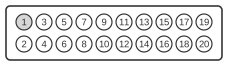
| Pin | Signal | Description |
|---|---|---|
| 1 | GND | Ground |
| 2 | PH0 | Phase 0: state control line |
| 3 | GND | Ground |
| 4 | PH1 | Phase 1: state control line |
| 5 | GND | Ground |
| 6 | PH2 | Phase 2: state control line |
| 7 | GND | Ground |
| 8 | PH3 | Phase 3: register write strobe |
| 9 | n.c. | Not connected |
| 10 | /WRREQ | Write data request |
| 11 | +5V | +5 volts |
| 12 | SEL | Head select |
| 13 | +12V | +12 volts |
| 14 | /ENBL | Drive enable |
| 15 | +12V | +12 volts |
| 16 | RD | Read data |
| 17 | +12V | +12 volts |
| 18 | WR | Write data |
| 19 | +12V | +12 volts |
| 20 | n.c. | Not connected |
Signals
- GND — Signal ground; interleaved with signal lines on odd pins 1, 3, 5, 7 to reduce noise on the ribbon cable.
- PH0–PH3 — Phase control lines (also labelled CA0/CA1/CA2/LSTRB in IWM/SWIM documentation); used by the controller to address internal drive registers and issue commands such as eject, motor on/off, and stepping direction.
- n.c. — Not connected (pins 9 and 20); reserved and must be left open.
- /WRREQ — Write request (active low); when asserted by the SWIM controller, the drive is enabled to accept serial write data on the WR line.
- +5V — Logic supply voltage for drive electronics.
- SEL — Head select; selects the upper or lower read/write head, required for double-sided 1.44 MB SuperDrive operation (equivalent to HDSEL on the DB-19 external connector).
- +12V — Motor supply voltage; provided on multiple pins (13, 15, 17, 19) to distribute current across the connector.
- /ENBL — Drive enable (active low); enables the drive and the read data path; the RD line is tri-stated when this signal is deasserted.
- RD — Read data; serial GCR- or MFM-encoded data from the drive to the SWIM controller.
- WR — Write data; serial GCR- or MFM-encoded data from the SWIM controller to the drive.
Notes
- This connector is for the internal Sony floppy mechanism only; it is not the same as the DB-19 external floppy port found on classic Macintosh and Apple II computers.
- The SWIM chip (Super Woz Integrated Machine, also called Sander-Wozniak Integrated Machine) replaced the earlier IWM in models from the Mac IIx and SE/30 onwards; it operates at 15.6672 MHz in Macintosh mode.
- The PH0–PH3 lines serve the same physical purpose as the CA0/CA1/CA2/LSTRB lines named in IWM register-access documentation — both naming conventions refer to the same conductors.
- Multiple +12 V pins share the motor supply load; all must be connected when fitting a replacement drive.