
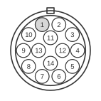
 14 pin DIN male connector at the diskdrive.
The Atari ST external floppy port uses a 14-pin circular DIN female socket on the computer, with a mating 14-pin DIN male plug on the drive cable. Introduced with the Atari 520ST and 1040ST in the mid-1980s, it interfaces one or two Shugart-derived MFM floppy drives (3.5-inch or 5.25-inch, double-density) via the Western Digital WD1772 floppy disk controller. The 14-pin connector collapses the 34 lines of the Shugart standard to just 14 by omitting Head Load, Density Select, Ready, and Disk Change signals; drive and side selection are managed by the YM2149 PSG I/O ports rather than dedicated connector lines.
| Pin | Name | Description |
|---|---|---|
| 1 | RD | Read Data |
| 2 | SIDE0 | Side 0 Select |
| 3 | GND | Ground |
| 4 | INDEX | Index |
| 5 | SEL0 | Drive 0 Select |
| 6 | SEL1 | Drive 1 Select |
| 7 | GND | Ground |
| 8 | MOTOR | Motor On |
| 9 | DIR | Direction In |
| 10 | STEP | Step |
| 11 | WD | Write Data |
| 12 | WG | Write Gate |
| 13 | TRK00 | Track 00 |
| 14 | WP | Write Protect |
Signals
- RD — MFM-encoded read data stream from the drive to the WD1772 FDC.
- SIDE0 — Side select: low selects side 0 (top head), high selects side 1.
- GND — Logic ground (pins 3 and 7).
- INDEX — Once-per-revolution index pulse from the drive spindle.
- SEL0 — Drive 0 select; behaviour depends on motherboard strap setting (W2 on STF, W300/W301 on STE).
- SEL1 — Drive 1 select; similarly governed by the same motherboard strap options.
- MOTOR — Motor on control, active low, energises the spindle motor of the selected drive.
- DIR — Step direction: sets whether the head steps inward (towards higher tracks) or outward.
- STEP — Step pulse; each falling edge moves the head by one track in the direction set by DIR.
- WD — MFM-encoded write data stream from the WD1772 to the drive.
- WG — Write gate; enables the write head when active.
- TRK00 — Track 00 indicator; asserted by the drive when the head is at track zero.
- WP — Write protect; asserted by the drive when the inserted disc is write-protected.
Notes
- The connector on the computer is a 14-pin DIN female socket (Atari part designation C070131); the mating plug on the drive cable is a 14-pin DIN male.
- Up to two floppy drives may be connected; the cable daisy-chains from drive 0 to drive 1.
- The READY and DISK CHANGE signals present in the Shugart 34-pin standard are absent from this connector; software must infer disc presence from index pulses and use polling rather than interrupt-driven change detection.
- Drive and side selection are controlled by outputs of the YM2149 PSG chip, not by dedicated FDC signals; the exact mapping of SEL0 and SEL1 to physical drives depends on the motherboard strap configuration.
- The FDC is the Western Digital WD1772, supporting single- and double-density MFM recording at 250 kbits/s for 300 RPM drives.
- Power to the floppy drive is supplied via a separate 4-pin power connector, not through the DIN14 signal cable.