
The ST506/412 interface is the de facto standard hard-drive interface introduced by Seagate in 1980 with the ST506 (5 MB, 5.25-inch) and extended with the ST412 (10 MB, 1981), which was adopted by IBM for the PC/XT. It uses two ribbon cables: a shared 34-pin control cable connecting the controller to up to two drives, and a separate 20-pin data cable for each drive carrying differential MFM or RLL data pairs. MFM (Modified Frequency Modulation) encoding runs at 5 Mbit/s, whilst RLL (2,7 Run-Length Limited) encoding operates at 7.5 Mbit/s, yielding approximately 50% greater storage capacity on compatible drives. The interface was never formally standardised but spread as an industry-wide de facto standard through compatible controller ICs such as the Western Digital WD1003.
 34 PIN IDC MALE at the Controller
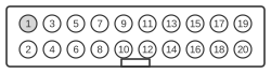 20 PIN IDC MALE at the Controller
 34 PIN IDC FEMALE at the Harddisk
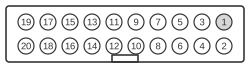 20 PIN IDC FEMALE at the Harddisk
Control connector
| Pin | Name |
|---|---|
| 2 | Head Sel 8 (was originally used as Reduced Write Current) |
| 4 | Head Sel 4 |
| 6 | Write Gate |
| 8 | Seek Complete |
| 10 | Track 0 |
| 12 | Write Fault |
| 14 | Head Sel 1 |
| 16 | RES (reserved) |
| 18 | Head Sel 2 |
| 20 | Index |
| 22 | Ready |
| 24 | Step |
| 26 | Drive Sel 1 |
| 28 | Drive Sel 2 |
| 30 | Drive Sel 3 |
| 32 | Drive Sel 4 |
| 34 | Direction In |
- All odd pins are GND, Ground.
- The control cable carries a twist covering conductors 25–29 on the segment leading to the furthest drive (drive C on most systems), used for drive selection by inverting the Drive Sel lines to that drive.
- The controller end uses a pin-type (male IDC) connector; the drive end uses a card-edge (female) connector. A keying notch prevents reversal.
Data connector
| Pin | Name | Description |
|---|---|---|
| 1 | Drive Selected | |
| 2 | GND | Ground |
| 3 | RES | (reserved) |
| 4 | RES | (reserved) |
| 5 | RES | (reserved) |
| 6 | RES | (reserved) |
| 7 | RES | (reserved) |
| 8 | RES | (reserved) |
| 9 | RES | (reserved) |
| 10 | RES | (reserved) |
| 11 | GND | Ground |
| 12 | GND | Ground |
| 13 | Write Data+ | |
| 14 | Write Data- | |
| 15 | GND | Ground |
| 16 | GND | Ground |
| 17 | Read Data+ | |
| 18 | Read Data- | |
| 19 | GND | Ground |
| 20 | GND | Ground |
Notes
- Each drive requires its own 20-pin data cable; the 34-pin control cable is shared (daisy-chained) between both drives.
- Electrical levels on the control cable are TTL open-collector: TRUE = 0.0–0.4 V DC (sink up to 48 mA); FALSE = 2.5–5.25 V DC (source up to 250 µA). All odd-numbered control pins are chassis ground.
- Data pairs on the 20-pin cable conform to the EIA RS-422 differential standard. Recommended connectors per the Seagate OEM specification are AMP 88373-3 (control, 34-pin) and AMP 88373-6 (data, 20-pin), or Molex equivalents.
- Power is supplied via a separate 4-pin AMP Mate-N-Lok connector (not shown): +12 V ±5% (1.6 A typical, 3.5 A at power-on) and +5 V ±5% (1.1 A typical); maximum ripple 50 mV peak-to-peak.
- The ST406, ST412, and ST419 share identical connector and interface specifications.
- RLL encoding (2,7 RLL) requires media certified for RLL; using RLL encoding on drives rated only for MFM may cause data errors.
Signals
Control connector (34-pin):
- Head Sel 8 — Selects head 8; originally also used as Reduced Write Current signal on early drives.
- Head Sel 4 — Selects head 4 (binary head address bit 2^2).
- Head Sel 2 — Selects head 2 (binary head address bit 2^1).
- Head Sel 1 — Selects head 1 (binary head address bit 2^0).
- Write Gate — Asserted by the controller to enable writing to the selected head/cylinder.
- Seek Complete — Asserted by the drive when a seek operation has finished and the head is settled.
- Track 0 — Asserted by the drive when the head is positioned over cylinder 0.
- Write Fault — Asserted by the drive to signal a write-protection or write-electronics fault condition.
- Index — Pulse generated once per spindle revolution indicating the start of the first sector.
- Ready — Asserted by the drive when it is spinning at speed and ready to accept commands.
- Step — Pulse from the controller that moves the head one track in the direction set by Direction In.
- Drive Sel 1–4 — One-of-four drive select lines; the controller asserts one to address the corresponding drive.
- Direction In — Sets seek direction: asserted = move heads towards centre (higher cylinder numbers).
Data connector (20-pin):
- Drive Selected — Asserted by the drive to confirm it has been selected via the control cable.
- +MFM Write Data / -MFM Write Data — RS-422 differential pair carrying encoded write data from the controller to the drive.
- +MFM Read Data / -MFM Read Data — RS-422 differential pair carrying encoded read data from the drive to the controller.
- RES (pins 3–10) — Reserved; not connected per the Seagate OEM specification.