
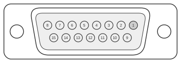
 15 pin D-SUB female connector at the computer.
The Sun-3 series workstations (circa 1985–1989) used a 15-pin D-sub (DB-15) female connector on the CPU back panel to interface with the Type 3 keyboard and mouse. Two independent full-duplex serial channels are carried on the connector: Channel A (pins 1 and 3) for keyboard data and Channel B (pins 5 and 7) for mouse data, both driven by a Zilog Z8530 Serial Communications Controller at RS-423 signal levels compatible with RS-232-C. The remaining pins are divided between ground returns and +5 VDC power rails. The Type 3 keyboard attaches via an integral coiled cable terminating in a male DB-15 plug, and the mouse connects to an RJ (phone-style) jack on the rear of the keyboard chassis.
| Pin | Name | Dir | Description |
|---|---|---|---|
| 1 | Keyboard In | IN | Keyboard In |
| 2 | GND | - | Ground |
| 3 | Keyboard Out | OUT | Keyboard Out |
| 4 | GND | - | Ground |
| 5 | Mouse In | IN | Mouse In |
| 6 | GND | - | Ground |
| 7 | Mouse Out | OUT | Mouse Out (!) |
| 8 | GND | - | Ground |
| 9 | GND | - | Ground |
| 10 | VCC | OUT | Power , +5 VDC |
| 11 | VCC | OUT | Power , +5 VDC |
| 12 | VCC | OUT | Power , +5 VDC |
| 13 | VCC | OUT | Power , +5 VDC |
| 14 | VCC | OUT | Power , +5 VDC |
| 15 | VCC | OUT | Power , +5 VDC |
Signals
- Keyboard In (RXD0) — receive data from keyboard to CPU, Channel A of the Z8530 SCC.
- Keyboard Out (TXD0) — transmit data from CPU to keyboard, Channel A of the Z8530 SCC.
- Mouse In (RXD1) — receive data from mouse to CPU, Channel B of the Z8530 SCC.
- Mouse Out (TXD1) — transmit data from CPU to mouse, Channel B of the Z8530 SCC.
- GND — signal and power return ground (pins 2, 4, 6, 8, 9).
- VCC — +5 VDC power supply to keyboard and mouse (pins 10–15).
Notes
- Direction is computer relative to keyboard/mouse.
- Signalling is RS-423, compatible with RS-232-C; the Z8530 SCC operates at 4.9152 MHz and supports up to 9.6 kbaud input and 19.2 kbaud output on each channel.
- Serial protocol: asynchronous, 1200 baud, 1 start bit, 8 data bits, 1 stop bit, no parity.
- Pin 13 is not listed in the Sun-3/75 Hardware Installation Manual signal table; it is likely not connected in practice despite appearing in the VCC group.
- This connector was superseded from the Sun-3/80 onward by an 8-pin mini-DIN carrying the same two serial channels at TTL levels.