
The Commodore Amiga CD32 (1993) exposes its keyboard interface through a 6-pin mini-DIN female connector mounted at the rear of the console. Unlike the 5-pin DIN used on earlier Amiga models, this connector doubles as a combined keyboard and serial auxiliary port, with serial signals running at 0–5 V logic levels rather than the ±12 V levels of conventional RS-232. The keyboard section uses the same synchronous open-collector KCLK/KDAT protocol as the wider Amiga family, with both lines pulled high and driven active-low. Swapping the clock and data pins causes runaway characters on screen.
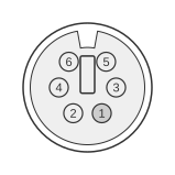 6 PIN MINI-DIN FEMALE (PS/2 STYLE) at the computer.
| Pin | Name | Dir | Description |
|---|---|---|---|
| 1 | /DATA | IN/OUT | Data |
| 2 | /TxD | OUT | Transmit Data (0-5V and reversed) |
| 3 | GND | - | Ground |
| 4 | +5V | OUT | +5 Volts DC (100 mA max) |
| 5 | CLOCK | IN | Clock |
| 6 | /RxD | IN | Receive Data (0-5V and reversed) |
Notes
- Direction is computer relative to keyboard.
- The serial lines (pins 2 and 6) operate at 0–5 V logic levels; there is no RS-232 level converter and no RTS/CTS hardware handshake.
- Keyboard signals are active-low: +5 V represents logic 0, 0 V represents logic 1.
- CLOCK (pin 5) is unidirectional, driven by the keyboard; DATA (pin 1) is bidirectional, driven by both keyboard and computer.
- Swapping pins 1 and 5 (data and clock) causes continuous erroneous character output.
Signals
- /DATA — Bidirectional keyboard data; active-low open-collector line with pull-up resistors at both ends; connects to the CIA-A SP pin.
- /TxD — Serial transmit data output from the computer; 0–5 V logic, active-low (signal label reflects inverted sense).
- GND — Signal and power ground reference.
- +5V — Power supply to the keyboard; 5 V DC.
- CLOCK — Unidirectional keyboard clock output; active-low open-collector; connects to the CIA-A CNT pin; approximately 17 kbit/s (60 µs per bit).
- /RxD — Serial receive data input to the computer; 0–5 V logic, active-low (signal label reflects inverted sense).