
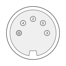
 (At the computer)
5 PIN DIN 180° (DIN41524) FEMALE (A1000/A2000/A3000) at the computer.
The Amiga keyboard interface uses a synchronous, open-collector serial bus with two signal lines: KCLK (clock) and KDAT (data). Both lines carry active-low signals, where +5 V represents logic 0 and 0 V represents logic 1, at a bit rate of approximately 17 kbits/sec (60 µs per bit). The A2000 and A3000 expose this bus via a 5-pin DIN 180° (DIN41524) female socket at the computer; the A1000 used a different 4-pin RJ-style connector, whilst the A500 uses an internal SIL header rather than an external DIN socket. KDAT connects to the SP pin of the 8520 CIA-A chip and is bidirectional, whilst KCLK connects to the CIA-A CNT pin and is driven only by the keyboard unit.
| Pin | A1000 | A2000/A3000 |
|---|---|---|
| 1 | +5 Volts | KCLK |
| 2 | CLOCK | KDAT |
| 3 | DATA | n/c |
| 4 | GND | GND |
| 5 | n/c | +5 Volts |
Signals
- KCLK — Keyboard clock; unidirectional, driven by the keyboard microprocessor; connects to the CIA-A CNT pin in the computer.
- KDAT — Keyboard data; bidirectional open-collector line; connects to the CIA-A SP pin. The computer pulses KDAT low for at least 85 µs as a handshake acknowledgement after each received byte.
- n/c — No connection (Pin 3 of the A2000/A3000 connector; Pin 5 of the A1000 connector).
- GND — Signal and power return.
- +5 V — Supply voltage to the keyboard unit.
Notes
- The connector shown is a 5-pin DIN 180° (DIN41524) female socket at the computer; the keyboard cable terminates in the corresponding male plug.
- Both KCLK and KDAT are open-collector lines with pull-up resistors present in both the keyboard microprocessor and the computer.
- Signal levels are active-low: +5 V = logic 0, 0 V = logic 1.
- 8-bit serial words are transmitted bit-rotated in the order 6-5-4-3-2-1-0-7.
- Key codes are sent for both key-down and key-up events; an upstroke code equals the downstroke value plus $80.
- The A1000 keyboard used a 4-pin RJ-style cable with a different pin assignment (Pin1=+5V, Pin2=CLOCK, Pin3=DATA, Pin4=GND). The Amiga Hardware Reference Manual Appendix E explicitly notes that the 5-pin DIN specification is “Not Applicable to the A500”; the A500 uses an internal connector, not an external DIN socket.
References
- Amiga Hardware Reference Manual, 2nd Edition — Addison-Wesley Publishing Company, Inc. (for Commodore-Amiga, Inc.), ISBN 0-201-18157-6, 1989
- Amiga Hardware Reference Manual, 3rd Edition — Commodore-Amiga, Inc., 1991