
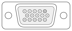
 15 pin highdensity D-SUB female connector at the computer.
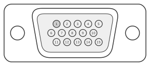 15 pin highdensity D-SUB male connector at the joystick cable.
The Enhanced Joystick Port (EJP) is Atari’s proprietary high-density 15-pin D-subminiature controller interface, introduced on the Atari STe and carried forward on the Falcon030 and Jaguar game console in the early 1990s. Unlike the older 9-pin DE-9 joystick ports found on earlier Atari computers, the EJP uses a three-row high-density shell — the same physical size as a 9-pin connector — and carries both digital direction lines and a pair of analogue-to-digital converter inputs for paddle or analogue joystick axes. The port appeared on the Atari STe, Falcon030, and Jaguar, as well as compatible C-Lab Falcon clones; it is not compatible with the earlier DE-9 joystick port or with the distinct 15-pin analogue port of the Atari 5200 SuperSystem.
| Pin | Name | Description |
|---|---|---|
| 1 | UP0 | Up 0 |
| 2 | DOWN0 | Down 0 |
| 3 | LEFT0 | Left 0 |
| 4 | RIGHT0 | Right 0 |
| 5 | PAD0Y | Paddle 0 Y |
| 6 | FIRE0/LIGHT GUN | Fire 0/Lightgun |
| 7 | VCC | +5 VDC |
| 8 | n/c | Not connected |
| 9 | GND | Ground |
| 10 | FIRE2 | Fire 2 |
| 11 | UP2 | Up 2 |
| 12 | DOWN2 | Down 2 |
| 13 | LEFT2 | Left 2 |
| 14 | RIGHT2 | Right 2 |
| 15 | PAD0X | Paddle 0 X |
Notes
The connector on the computer is a female high-density 15-pin D-sub (three rows of five pins); the controller plug is the corresponding male. The high-density shell shares its outer dimensions with a standard 9-pin D-sub and must not be confused with the larger, two-row normal-density 15-pin connector used for VGA and similar interfaces. The pin numbering, viewed from the front of the computer port, runs 5–1 across the top row, 10–6 across the middle row, and 15–11 across the bottom row. Port A and Port B share the same pin assignment; Pin 6 doubles as a light-gun signal input on Port A. Pin 8 is defined as not connected in the Falcon030 manual pinout.
Signals
- UP0 — Direction up, joystick 0 (active low)
- DOWN0 — Direction down, joystick 0 (active low)
- LEFT0 — Direction left, joystick 0 (active low)
- RIGHT0 — Direction right, joystick 0 (active low)
- PAD0Y — Analogue paddle / joystick Y-axis input, controller 0; connected to the Y-axis ADC
- FIRE0/LIGHT GUN — Fire button, joystick 0; also serves as the light-gun pulse input on Port A
- VCC — +5 V DC supply to controller
- n/c — Not connected
- GND — Ground / 0 V reference
- FIRE2 — Fire button, joystick 2 (second controller within the same port)
- UP2 — Direction up, joystick 2 (active low)
- DOWN2 — Direction down, joystick 2 (active low)
- LEFT2 — Direction left, joystick 2 (active low)
- RIGHT2 — Direction right, joystick 2 (active low)
- PAD0X — Analogue paddle / joystick X-axis input, controller 0; connected to the X-axis ADC
References
- Atari Falcon030 Developer Documentation; Atari STe Hardware Reference — Atari Corporation