
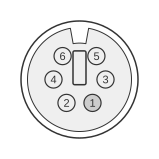
 6 PIN MINI-DIN FEMALE (PS/2 STYLE) at the computer.
IBM introduced the 6-pin mini-DIN keyboard connector with the Personal System/2 (PS/2) range in 1987, replacing the 5-pin DIN used on the PC/XT and AT. The connector carries the same bidirectional serial protocol as the AT keyboard — 11-bit frames at TTL levels over open-collector Clock and Data lines — with the only change being the smaller circular housing. The interface logic for the keyboard and the pointing device is identical, and both connectors are electrically interchangeable. Pins 2 and 6 are designated Reserved by IBM and are not intended as unconnected spare pins.
| Pin | Name | Dir | Description |
|---|---|---|---|
| 1 | DATA | IN/OUT | Key Data |
| 2 | Res | - | Reserved |
| 3 | GND | - | Gnd |
| 4 | VCC | OUT | Power , +5 VDC |
| 5 | CLK | OUT | Clock |
| 6 | Res | - | Reserved |
Notes
- Direction is computer relative to keyboard.
- The 6-pin mini-DIN connector is keyed so that it can only be inserted in one orientation.
- The keyboard and pointing-device (mouse) ports on PS/2 systems use identical connectors and identical interface logic; either device may be plugged into either port electrically, though the system BIOS typically expects each device on its designated socket.
- Pins 2 and 6 are Reserved per the IBM PS/2 Hardware Interface Technical Reference; they are not general-purpose unconnected pins.
- Clock and Data lines are open-collector, pulled to +5 Vdc; logic levels are TTL-compatible. The host may inhibit communication by pulling CLK low.
Signals
- DATA — Bidirectional serial data line carrying keyboard scan codes (make and break) using an 11-bit frame: start bit, 8 data bits, odd parity bit, stop bit.
- CLK — Clock generated by the keyboard to synchronise the data signal; the host may hold CLK low to inhibit the keyboard.
- GND — Common ground; reference for data signals and return path for power.
- VCC — +5 Vdc supply to the keyboard from the host system.