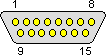
 15 pin D-SUB male connector at the
Atari.
15 pin D-SUB male connector at the
Atari.
| Pin | Description |
|---|---|
| 1 | Keypad – right column |
| 2 | Keypad – middle column |
| 3 | Keypad – left column |
| 4 | Start, Pause, and Reset common |
| 5 | Keypad – third row and Reset |
| 6 | Keypad – second row and Pause |
| 7 | Keypad – top row and Start |
| 8 | Keypad – bottom row |
| 9 | Pot common |
| 10 | Horizontal pot (POT0, 2, 4, 6) |
| 11 | Vertical pot (POT1, 3, 5, 7) |
| 12 | 5 volts DC |
| 13 | Bottom side buttons (TRIG0, 1, 2, 3) |
| 14 | Top side buttons |
| 15 | 0 volts – ground |
It"s handy to consider the keypad in a matrix format:
| Pin | 4 | 3 | 2 | 1 |
|---|---|---|---|---|
| 7 | Start | 1 | 2 | 3 |
| 6 | Pause | 4 | 5 | 6 |
| 5 | Reset | 7 | 8 | 9 |
| 8 | - | 0 | 1. |
For instance, mashing button 5 makes a connection between pins 2 and 6.
Analog Direction Inputs
Potentiometer inputs are 0-500kohm, linear. Directional inputs are read by a RC delay circuit, i.e. the time it takes a capacitor to recharge after being discharged determines the potentiometer positions.
- North=0 ohm between pins 9 and 11
- South=500 ohms between pins 9 and 11
- West=0 ohm between pins 9 and 10
- East=500 ohms between pins 9 and 10