
The Commodore C16, C116, and Plus/4 computers use an 8-pin mini-DIN connector for their joystick ports, physically distinct from the 9-pin DE-9 socket found on the Commodore 64 and VIC-20. The electrical signalling follows the same active-low convention: pressing a direction or the fire button shorts the corresponding pin to ground. Both joystick ports share the same physical connector, with pin 8 acting as a SELECT line that the TED chip uses to distinguish Joy 1 from Joy 2. An adapter is required to use standard DE-9 joysticks with these machines.
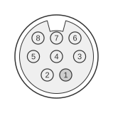 8 PIN MINI-DIN FEMALE at the computer
Joystick 1
| Pin | Name | Dir | Comment |
|---|---|---|---|
| 1 | JOYA0 | IN | UP |
| 2 | JOYA1 | IN | DOWN |
| 3 | JOYA2 | IN | LEFT |
| 4 | JOYA3 | IN | RIGHT |
| 5 | +5VDC | OUT | |
| 6 | BUTTON A | ? | |
| 7 | GND | - | |
| 8 | COMMON A ? | ? | Is connected to DATA2 thru a buffer. |
Joystick 2
| Pin | Name | Dir | Comment |
|---|---|---|---|
| 1 | JOYB0 | IN | UP |
| 2 | JOYB1 | IN | DOWN |
| 3 | JOYB2 | IN | LEFT |
| 4 | JOYB3 | IN | RIGHT |
| 5 | +5VDC | OUT | |
| 6 | BUTTON B | ? | |
| 7 | GND | - | |
| 8 | COMMON B ? | ? | Is connected to DATA1 thru a buffer. |
Notes
- Direction is computer relative to device.
- The 8-pin mini-DIN is not mechanically compatible with the 9-pin DE-9 joystick connector used on the Commodore 64 and VIC-20; an adapter is required to use standard Atari-compatible joysticks.
- Pin 8 (COMMON) is the SELECT line used by the TED chip to determine which joystick port is being addressed; it is tied to joystick signal ground via a buffer.
- Autofire joysticks that drive the SELECT line (pin 8) with active voltage may damage the TED chip; use of such peripherals is not recommended.
Signals
- JOYA0 / JOYB0 — Up direction; active-low, pulled high internally; grounded when joystick is pushed forward.
- JOYA1 / JOYB1 — Down direction; active-low.
- JOYA2 / JOYB2 — Left direction; active-low.
- JOYA3 / JOYB3 — Right direction; active-low.
- +5VDC — 5 V supply output from the computer; powers autofire circuitry in compatible joysticks.
- BUTTON A / BUTTON B — Fire button; active-low. Direction not fully documented.
- GND — Signal ground.
- COMMON A / COMMON B — SELECT line connecting to DATA2 (Joy 1) or DATA1 (Joy 2) via a buffer; used by the TED chip to address each port independently. Full electrical behaviour not publicly documented.