
The IBM Game Control Adapter, introduced in 1981, uses a DA-15 (15-pin D-sub) female connector at the computer to support up to two analogue joysticks with four potentiometer axes and four buttons, accessed via I/O port 201h. Sound Blaster and compatible sound cards from 1989 onwards repurposed two pins of this connector to carry MIDI signals: pin 12 (originally assigned as ground for buttons 3 and 4 in some implementations) became MIDI Transmit, and pin 15 (originally not connected in the IBM specification) became MIDI Receive. This MIDI-via-game-port scheme is a Creative Labs extension, not part of the original IBM Game Control Adapter specification.
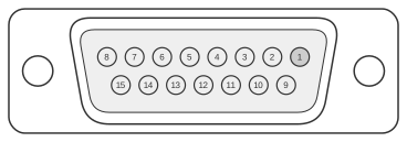 15 PIN D-SUB FEMALE at the computer
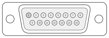 15 PIN D-SUB MALE at the joystick cable.
| Pin | Name | Dir | Description |
|---|---|---|---|
| 1 | +5V | OUT | +5 VDC |
| 2 | /B1 | IN | Button 1 |
| 3 | X1 | IN | Joystick 1 - X |
| 4 | GND | - | Ground |
| 5 | GND | - | Ground |
| 6 | Y1 | IN | Joystick 1 - Y |
| 7 | /B2 | IN | Button 2 |
| 8 | +5V | OUT | +5 VDC |
| 9 | +5V | OUT | +5 VDC |
| 10 | /B4 | IN | Button 4 |
| 11 | X2 | IN | Joystick 2 - X |
| 12 | MIDITXD | OUT | MIDI Transmit |
| 13 | Y2 | IN | Joystick 2 - Y |
| 14 | /B3 | IN | Button 3 |
| 15 | MIDIRXD | IN | MIDI Receive |
Notes
- Direction is computer relative to joystick.
- Joystick axes use 0–100 kΩ potentiometers; axis position is read by timing a monostable pulse via NE558 quad timer.
- Pins 12 and 15 carry MIDI signals only on Sound Blaster and compatible sound cards; they are not connected (or are used for ground/buttons) on the original IBM Game Control Adapter.
- Pin 8 carries +5 V on Sound Blaster cards to power an external MIDI adapter breakout cable; this is a sound-card extension and is not defined in the IBM Game Control Adapter specification.
- MIDI operates at 31.25 kbps ±1% using a current-loop, opto-isolated interface; MIDI TX and RX on pins 12 and 15 connect to a passive breakout cable that provides standard 5-pin DIN MIDI IN and MIDI OUT sockets.
Signals
- +5V — +5 VDC supply from the host (pins 1, 8, 9); used to power joystick potentiometers and, on sound cards, the MIDI breakout adapter
- /B1 — Button 1, active low; joystick 1, trigger button
- X1 — Joystick 1 X-axis, analogue; resistance to ground determines axis position
- GND — Ground reference (pins 4, 5)
- Y1 — Joystick 1 Y-axis, analogue
- /B2 — Button 2, active low; joystick 1, second button
- /B4 — Button 4, active low; joystick 2, second button
- X2 — Joystick 2 X-axis, analogue
- MIDITXD — MIDI Transmit Data (computer to MIDI device); Sound Blaster extension on pin 12; 31.25 kbps serial
- Y2 — Joystick 2 Y-axis, analogue
- /B3 — Button 3, active low; joystick 2, trigger button
- MIDIRXD — MIDI Receive Data (MIDI device to computer); Sound Blaster extension on pin 15; 31.25 kbps serial
About MIDI Signals
How MIDI messages are structured
MIDI messages consist of a status byte followed by zero or more data bytes. The status byte identifies the message type and, for channel messages, the target channel. Data bytes always have bit 7 clear (value 0–127), while status bytes have bit 7 set.
For example, a Note Off event on channel 0 is transmitted as three bytes: a status byte (1000 0000), a key number byte (0kkk kkkk), and a velocity byte (0vvv vvvv).
Bytes table
| Type | Command | Byte |
|---|---|---|
| 7 | 6 | 5 |
| Data | Data | Data |
| Channel | Note off event | 1000 |
| Note on event | 1001 | Channel |
| Polyphonic key pressure | 1010 | Channel |
| Control change | 1011 | Channel |
| Program change | 1100 | Channel |
| Channel pressure | 1101 | Channel |
| Pitch wheel change | 1110 | Channel |
| System Exclusive | System Exclusive Header | 1111 0000 |
| System Common | (Undefined) | 1111 0001 |
| Measure Information | 1111 0010 | |
| Song Select | 1111 0011 | |
| (Undefined) | 1111 0100 | |
| (Undefined) | 1111 0101 | |
| Tune Request | 1111 0110 | |
| System Exclusive | System Exclusive End of block | 1111 0111 |
| System Real Time | Timing Clock In Play | 1111 1000 |
| Measure End | 1111 1001 | |
| Start From 1st Measure | 1111 1010 | |
| Continue Start | 1111 1011 | |
| Timing Clock In End | 1111 1100 | |
| ? | 1111 1101 | |
| Active Sensing | 1111 1110 | |
| System Reset | System Reset | 1111 1111 |
Channel Signals
The four highest bits of a channel status byte identify the message type; the four lowest bits identify the channel (0–15). Note off event (key, velocity) Note on event (key, velocity) Polyphonic key pressure (key, after-touch) Control change (command address, command value) Program change (program number) Channel pressure (after-touch) Pitch wheel change (value lsb, value msb)
System Exclusive
These two messages are used to send device-specific data. A System Exclusive block begins with a header byte, followed by a manufacturer identification code, one or more data blocks, and a System Exclusive End of Block byte. System Exclusive Header + Data (Identification code) + Data block(s) + System Exclusive End of block
System Real Time
Real-time messages are used for synchronisation and are sent on all channels. Timing Clock In Play Transmitted while the system is in play mode; 24 clock pulses per quarter note. Measure End Replaces the Timing Clock In Play signal at the end of each measure. Start From 1st Measure Sent when the master play key is pressed; the first Timing Clock In Play must follow within 5 ms. Continue Start Sent when the master continue key is pressed; the next Timing Clock In Play must follow within 5 ms. Timing Clock In End Sent when the master is in wait mode; used to maintain PLL lock during a pause. Active Sensing Periodic keep-alive message transmitted every 300 ms to indicate that the connection is active.
System Common
Measure Information (measure number lsb, measure number msb) Song Select (song number) Tune Request
System Reset
System Reset Resets the entire system to its power-up state.
Parameters
Channel Channel number from 0 to 15. Key Key number from 0 to 127; middle C is number 60. Velocity Velocity from 0 to 127 (0 = Note off). If the keyboard does not support velocity, 64 is sent as a default. After touch After-touch from 0 to 127. Command address Address from 0 to 127. Command value For controllers, from 0 to 127. For switches, 0 = off, 127 = on (other values are ignored). Program number Program number from 0 to 127. Identification code Manufacturer code from 0 to 127.
| 01 | 000 0001 | Sequential Systems |
| 40 | 100 0000 | Kawai |
| 41 | 100 0001 | Roland |
| 42 | 100 0010 | Korg |
| 43 | 100 0011 | Yamaha |
Measure number Measure number in 14 bits, split into 7 LSB bits and 7 MSB bits transmitted as two data bytes.
References
- Sound Blaster Series Hardware Programming Guide (Creative Technology Ltd., 1996)
- Roland MPU-401 MIDI Processing Unit Technical Reference Manual (Roland Corporation, May 1985)
- IBM Personal Computer AT Technical Reference, document 1502494, IBM Corporation, March 1984