
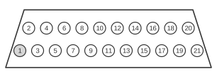
 21 PIN SCART MALE to the TV
21 PIN SCART MALE to the Video Recorder
SCART (also known as Péritel or EuroAV) is a 21-pin trapezoidal connector standardised as CENELEC EN 50049-1 and IEC 60933-1, developed in France during the mid-1970s and widely adopted across Europe from the mid-1980s onwards. A single cable carries bidirectional stereo audio, composite video (1 V p-p, 75 Ω), and optionally RGB or S-Video signals between consumer AV equipment such as televisions and video recorders. Pin 8 controls function and aspect-ratio switching, while pin 16 selects between composite/S-Video and RGB modes.
| TV | VCR |
|---|---|
| Audio Right Out | 1 |
| Audio Right In | 2 |
| Audio Left Out | 3 |
| Audio Left In | 6 |
| Audio Ground | 4 |
| Red | 15 |
| Red Ground | 13 |
| Green | 11 |
| Green Ground | 9 |
| Blue | 7 |
| Blue Ground | 5 |
| Status / 16:9 | 8 |
| Reserved | 10 |
| Reserved | 12 |
| Fast Blanking Ground | 14 |
| Fast Blanking | 16 |
| Video Out Ground | 17 |
| Video In Ground | 18 |
| Video Out | 19 |
| Video In | 20 |
| Ground | 21 |
Signals
- Audio Right Out / In (pins 1, 2) — right-channel audio; 0.5 V rms, output impedance <1 kΩ, input impedance >10 kΩ
- Audio Left Out / In (pins 3, 6) — left-channel audio; same levels as right channel
- Audio Ground (pin 4) — common ground for both audio channels
- Red (pin 15) — RGB red signal input to TV; 0.7 V p-p, 75 Ω (Table 1 RGB mode)
- Red Ground (pin 13) — ground for the red/chrominance line
- Green (pin 11) — RGB green signal input to TV; 0.7 V p-p, 75 Ω
- Green Ground (pin 9) — ground for the green signal
- Blue (pin 7) — RGB blue signal input to TV; 0.7 V p-p, 75 Ω
- Blue Ground (pin 5) — ground for the blue signal
- Status / 16:9 (pin 8) — function/aspect-ratio switching: 0–2 V = 4:3; 4–8 V = 16:9 widescreen; 9.5–12 V = external device connected
- Reserved (pins 10, 12) — reserved for D2B digital bus; typically unused in standard VCR cables
- Fast Blanking Ground (pin 14) — ground for the fast-blanking signal
- Fast Blanking (pin 16) — mode select: 0–0.4 V = composite video or S-Video mode; 1–3 V = RGB mode
- Video Out Ground (pin 17) — ground for the composite video output (pin 19)
- Video In Ground (pin 18) — ground for the fast-blanking and composite video input lines
- Video Out (pin 19) — composite video output from TV to VCR; 1 V p-p including sync, 75 Ω
- Video In (pin 20) — composite video input to TV from VCR; 1 V p-p including sync, 75 Ω
- Ground (pin 21) — chassis and shield ground
Notes
The connector is trapezoidal and polarised; it cannot be inserted incorrectly. All signal lines run at standard consumer levels with 75 Ω termination for video and >10 kΩ input impedance for audio. RGB and S-Video are mutually exclusive on the same socket because pin 15 carries Red in RGB mode (Table 1) and Chrominance in S-Video mode (Table 2). To enable RGB output from a VCR, pin 16 must be driven to 1–3 V by the source device; without this, the TV defaults to composite video display.