
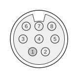
 Minidin 8 Pin Male (To the ATI video card)
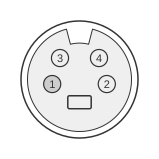 Minidin 4 pin Male (To the S-Video device Input)
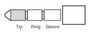 stereo 3,5mm audio jack male (To audio input device)
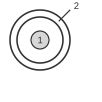 RCA male (To the Composite Video device Input)
The ATI All-in-Wonder output adapter is a proprietary 3-headed breakout cable supplied with All-in-Wonder graphics cards from the PRO and 128 era (circa 1998) through the Radeon and 9200 generations. It connects to the card’s A/V OUT bracket connector via an 8-pin Mini-DIN male plug, then fans out to a 4-pin Mini-DIN male (S-Video), an RCA male (composite video), and a 3.5 mm stereo jack male (audio). The S-Video path carries only luma and chroma signals — separate left and right audio RCA cables are always required alongside it. Composite video follows standard CVBS signalling at 1 Vp-p into 75 Ω; the output supports both NTSC and PAL televisions as well as VCRs, with European sets typically connected via an additional SCART adapter.
| Signal | ATI connector | S-Video | RCA Composite Video | Audio jack |
|---|---|---|---|---|
| Composite Video Signal | 1 | signal | ||
| Composite Video Ground | 2 | ground | ||
| Audio Ground | 3 | ground | ||
| Audio Right Signal | 4 | R (right) | ||
| Ground | 5 | 1, 2 | ||
| Color (Chrominance) | 6 | 4 | ||
| Audio Left Signal | 7 | L (left) | ||
| Intensity (Luminance) | 8 | 3 | ||
| Ground | shield | shield |
Notes
- The card-end connector is an 8-pin Mini-DIN male; the matching socket on the ATI All-in-Wonder card bracket is labelled A/V OUT.
- S-Video (4-pin Mini-DIN, ITU-R BT.470 / SMPTE S-Video standard) carries only luma (Y) and chroma (C); it does not carry audio. Left and right audio connections are always required in addition when using the S-Video output.
- S-Video delivers higher picture quality than composite video because the luminance and chrominance signals remain separated.
- Connecting audio to a VCR requires a cable with two RCA plugs at the TV/VCR end and a 3.5 mm stereo phone plug at the card-adapter end.
- Composite video signal level: 1 Vp-p, 75 Ω, unbalanced (standard CVBS).
- European televisions may be connected via a SCART adapter using the composite video and audio outputs.
- The 8-pin Mini-DIN wiring between the card connector and the adapter heads is proprietary to ATI; ATI’s installation manuals describe the adapter’s external connectors and purpose but do not publish a pin-level wiring table for the card-end Mini-DIN.
Signals
- Composite Video Signal — CVBS analogue video output; connects to the RCA composite input on a TV or VCR.
- Composite Video Ground — signal return for the composite video path.
- Audio Ground — signal return for both stereo audio channels.
- Audio Right Signal — analogue right-channel audio output; connects to the right (red) RCA audio input.
- Ground — shared ground for the S-Video connector pins 1 and 2 (outer shield and ground).
- Color (Chrominance) — chroma (C) component of the S-Video signal; connects to S-Video pin 4.
- Audio Left Signal — analogue left-channel audio output; connects to the left (white) RCA audio input.
- Intensity (Luminance) — luma (Y) component of the S-Video signal; connects to S-Video pin 3.
References
- ATI Technologies All-in-Wonder Radeon / 128 PRO / 128 Installation and Setup User’s Manual
- ATI Technologies All-in-Wonder PRO Installation and Setup User’s Guide v4.0
- ATI All-in-Wonder 128 / 128 PRO Installation and Setup User’s Guide v3.0
- ATI Technologies All-in-Wonder 9200 Installation and Setup User’s Manual