
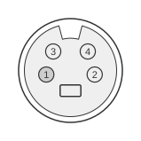
 S-VHS MALE connector
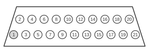 21 PIN SCART MALE Connector
An S-VHS-to-SCART adapter cable connects a Super-VHS source — such as a VCR or camcorder equipped with a 4-pin mini-DIN socket — to a television or display fitted with a 21-pin SCART (Péritel / EuroAV) socket. The SCART connector is standardised as IEC 60933-1:1988 and CENELEC EN 50049-1:1997, which define a Table 2 S-Video mode that routes luminance (Y, 1 V p-p, 75 Ω) to SCART pin 20 and chrominance (C, 0.3 V burst, 75 Ω) to SCART pin 15. The S-VHS connector was developed by JVC for S-VHS and Hi8 equipment from 1987 onwards; its separated Y/C signal avoids the luma/chroma interference present in composite video, yielding noticeably sharper and more accurate colour reproduction.
| S-VHS | => | SCART |
|---|---|---|
| Ground (Y) | 1 | 17 |
| Ground (C) | 2 | 17 |
| Y - Intensity (Luminance) | 3 | 20 |
| C - Color (Chrominance) | 4 | 15 |
Notes
- Both S-VHS ground pins (pin 1, Y ground; pin 2, C ground) are connected to SCART pin 17 (luminance/composite video ground) in this simplified wiring. EN 50049-1 Table 2 designates SCART pin 13 as the chrominance ground; some implementations therefore connect S-VHS pin 2 to SCART pin 13 instead of pin 17. Both approaches function correctly for a passive cable.
- SCART pin 16 (fast-blanking) may need to be held at 0–0.4 V to select S-Video (Y/C) mode on the television rather than RGB mode.
- SCART pin 8 (function/aspect-ratio switching) can be pulled to 1–3 V to signal that an external device is connected.
- The S-VHS mini-DIN connector is keyed; ensure the correct orientation before insertion to avoid bent pins.
Signals
S-VHS (4-pin mini-DIN)
- Pin 1 — Ground (Y) — signal ground for the luminance channel
- Pin 2 — Ground (C) — signal ground for the chrominance channel
- Pin 3 — Y (Luminance) — separated luminance signal, 1 V p-p, 75 Ω
- Pin 4 — C (Chrominance) — separated chrominance signal, 0.3 V burst (PAL), 75 Ω
SCART (21-pin)
- Pin 15 — Chrominance Input — receives C signal from S-VHS pin 4 in Table 2 S-Video mode (0.3 V burst, 75 Ω)
- Pin 17 — Ground — luminance/composite video ground; receives both S-VHS ground pins in this wiring
- Pin 20 — Luminance Input — receives Y signal from S-VHS pin 3 in Table 2 S-Video mode (1 V p-p, 75 Ω)