
 9 PIN D-SUB MALE to the Computer
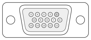 15 PIN HIGHDENSITY D-SUB FEMALE to the Monitor
This passive adapter connects a 9-pin DE-9 analogue RGB video source to the standard VGA HD-15 (three-row high-density DE-15) monitor input. The 9-pin analogue RGB format was used on the IBM Professional Graphics Controller (1984) and later on some SVGA breakout cables; it carries the same RGB signal levels as VGA — 0–0.7 V peak-to-peak into 75 Ω per channel — with TTL-level HSync and VSync. IBM introduced the HD-15 VGA connector with the PS/2 family in 1987, replacing the earlier 9-pin format. The RGB signal pairs map straight across (pins 1–3 and grounds 6–8), whilst the sync signals cross to HD-15 pins 13 and 14; the single sync ground on pin 9 is wired to both HD-15 pins 10 and 11.
| 9-Pin | 15-Pin | |
|---|---|---|
| Red Video | 1 | 1 |
| Green Video | 2 | 2 |
| Blue Video | 3 | 3 |
| Horizontal Sync | 4 | 13 |
| Vertical Sync | 5 | 14 |
| Red GND | 6 | 6 |
| Green GND | 7 | 7 |
| Blue GND | 8 | 8 |
| Sync GND | 9 | 10 + 11 |
Notes
The adapter is passive; no active circuitry is required because both connectors carry the same analogue RGB signal levels (0–0.7 V, 75 Ω). HD-15 pin 10 is the standard sync ground in VGA; pin 11 is the legacy Monitor-ID bit 0, which many monitors expect to be grounded to indicate a colour display — wiring the single sync ground (9-pin pin 9) to both is therefore consistent with common adapter practice. HD-15 pin 9 was an absent key pin in IBM’s original 1987 VGA definition and carries no signal in this adapter; VESA later defined it as a +5 V DDC supply in DDC-capable monitors. Legacy Monitor-ID bits on HD-15 pins 4, 11, 12, and 15 were superseded by VESA DDC (first published 1994), which repurposed pins 12 and 15 as I²C SDA and SCL respectively for reading EDID data.
Signals
- Red Video — analogue red component, 0–0.7 V p-p, 75 Ω terminated
- Green Video — analogue green component, 0–0.7 V p-p, 75 Ω terminated
- Blue Video — analogue blue component, 0–0.7 V p-p, 75 Ω terminated
- Horizontal Sync — TTL-level horizontal synchronisation pulse
- Vertical Sync — TTL-level vertical synchronisation pulse
- Red GND — ground return for red video signal
- Green GND — ground return for green video signal
- Blue GND — ground return for blue video signal
- Sync GND — ground return for sync signals; connected to both HD-15 pin 10 (sync ground) and pin 11 (legacy Monitor-ID bit 0, grounded to indicate colour display)