
The DMA Expansion Slot is the rear-panel expansion interface of the Commodore CDTV (CD1000), introduced in 1991. It is a 30-pin card-edge connector (designators CN10/CN11 in the CDTV Service Manual, PN 400403-01) with 2.54 mm pitch, accessible by removing the rear panel marked “Expansion”. The slot carries an 8-bit data bus (SD0–SD7) and an 8-bit address bus (A1–A8), together with Intel-style I/O control lines and DMA handshaking signals, all routed to the DMAC inside the CDTV — the same Western Digital DMA controller used in the Commodore A2091 and A590 hard disk controllers. Expansion cards designed for this slot must supply their own SCSI or LAN controller logic; the CDTV’s DMAC also services the internal CD-ROM drive, so DMA bandwidth is shared with any installed card.
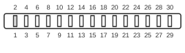
30 PIN CONNECTOR at the computer.
| Pin | Name | Description |
|---|---|---|
| 1 | GND | Ground |
| 2 | GND | Ground |
| 3 | VCC | +5 VDC |
| 4 | VCC | +5 VDC |
| 5 | SD1 | Data Bus 1 |
| 6 | SD0 | Data Bus 0 |
| 7 | SD3 | Data Bus 3 |
| 8 | SD2 | Data Bus 2 |
| 9 | SD5 | Data Bus 5 |
| 10 | SD4 | Data Bus 4 |
| 11 | SD7 | Data Bus 7 |
| 12 | SD6 | Data Bus 6 |
| 13 | /SDREQ | DMA Request |
| 14 | /INTX | Interrupt Request |
| 15 | /CSS | Chip Select |
| 16 | /SDACK | DMA Acknowledge |
| 17 | /IOR | I/O Read |
| 18 | /IOW | I/O Write |
| 19 | A8 | Address Bus 8 |
| 20 | 7M | 7.16 MHz System Clock |
| 21 | A6 | Address Bus 6 |
| 22 | A7 | Address Bus 7 |
| 23 | A4 | Address Bus 4 |
| 24 | A5 | Address Bus 5 |
| 25 | A2 | Address Bus 2 |
| 26 | A3 | Address Bus 3 |
| 27 | /IFRST | +5 VDC |
| 28 | A1 | Address Bus 1 |
| 29 | GND | Ground |
| 30 | GND | Ground |
Notes
- The connector is a 30-pin card-edge (60-contact physical edge) with 2.54 mm (0.1-inch) pitch.
- The slot is reached by removing the rear expansion panel; it is an internal interface, not directly accessible from outside the unit.
- The data bus is 8 bits wide (SD0–SD7); this is by design and differs from the full 16-bit 68000 bus exposed on the Diagnostic Slot.
- The address bus provides only eight lines (A1–A8), sufficient for addressing peripheral registers on expansion cards.
- The DMAC also drives the internal CD-ROM drive; DMA bandwidth on this slot is shared with that device.
- Pin 27 (/IFRST) is labelled as a reset line in the source documentation; the table description “+5 VDC” appears to be a pre-existing labelling anomaly — treat the signal as an active-low interface reset.
- Power pins (VCC) are rated at +5 V; no −5 V or +12 V rails are present on this slot.
Signals
- GND — Signal and power ground (pins 1, 2, 29, 30).
- VCC — +5 V supply to expansion card (pins 3, 4).
- SD0–SD7 — 8-bit bidirectional data bus connecting the expansion card to the DMAC.
- /SDREQ — DMA Request; asserted by the expansion card to request a DMA transfer cycle.
- /INTX — Interrupt Request; asserted by the expansion card to signal an interrupt condition to the host.
- /CSS — Chip Select; asserted by the DMAC to select the expansion card for an I/O transaction.
- /SDACK — DMA Acknowledge; asserted by the DMAC to grant a requested DMA transfer.
- /IOR — I/O Read; Intel-style strobe indicating the host is reading from the card.
- /IOW — I/O Write; Intel-style strobe indicating the host is writing to the card.
- A1–A8 — 8-bit address bus used to select registers within the expansion card.
- 7M — 7 MHz system clock derived from the CDTV’s master oscillator (7.15909 MHz NTSC / 7.09379 MHz PAL).
- /IFRST — Interface Reset; active-low reset line for the expansion slot.