
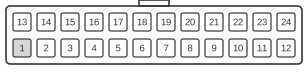
 24 pin MOLEX 44206-0007 connector at the motherboard (MOLEX 39-29-9242).
24 pin MOLEX 39-01-2240 or equivalent connector at the cable.
WTX (Workstation Technology Extended) is a motherboard and power supply form factor introduced by Intel in September 1998, targeting mid-range workstations built around dual 32-bit or 64-bit Intel processors. The connector family is governed by the WTX Power Supply Design Guidelines (Intel, Version 1.0, February 1999), which forms part of the broader WTX Workstation System Specification Version 1.02. The P1 connector shown here is the primary required 24-pin (2×12) supply, using Molex Mini-Fit Jr. housings, and delivers the +3.3 V and +5 V rails to the motherboard chipset and I/O subsystem alongside two always-present standby voltages. Although physically similar to the later ATX 24-pin connector, WTX P1 carries different signal assignments and is electrically incompatible with ATX.
| Pin | Name | Color | Description |
|---|---|---|---|
| 1 | 3.3V | orange | +3.3 VDC |
| 2 | 3.3V | orange | +3.3 VDC |
| 3 | 3.3V | orange | +3.3 VDC |
| 4 | 3.3V | orange | +3.3 VDC |
| 5 | 3.3V | orange | +3.3 VDC |
| 6 | com | black | Ground |
| 7 | com | black | Ground |
| 8 | com | black | Ground |
| 9 | com | black | Ground |
| 10 | com | black | Ground |
| 11 | 5V | red | +5 VDC |
| 12 | 5V | red | +5 VDC |
| 13 | 3.3V | orange | +3.3 VDC |
| 14 | 3.3V | orange | +3.3 VDC |
| 15 | 3.3V | orange | +3.3 VDC |
| 16 | 3.3V | orange | +3.3 VDC |
| 17 | 3.3Vaux | brown | +3.3 VDC Auxilary |
| 18 | com | black | Ground |
| 19 | com | black | Ground |
| 20 | com | black | Ground |
| 21 | com | black | Ground |
| 22 | 5Vsb | purple | +5 VDC Standby |
| 23 | 5V | red | +5 VDC |
| 24 | 5V | red | +5 VDC |
Notes
P1 is the primary required connector and must be mated before the PSU is powered. The board-side housing is Molex 39-29-9242 (Mini-Fit Jr., 24-circuit, right-angle or vertical); the cable-side housing is Molex 39-01-2240. The connector is keyed and polarised, preventing reverse insertion. A second required connector (P2, 22-pin) carries all control signals — including PS-ON#, PS-OK, SLEEP#, FanC, FanM, and the 12 V_IO rail — and must also be connected for normal operation. Optional P3 (8-pin) and P4/P5 (6-pin each) connectors supply separate 12 V rails to memory DC-DC converters and processor Power Pods. The +3.3 V rail is regulated to ±4 % (3.17–3.43 V) and the +5 V rail to ±4 % (4.80–5.20 V). Remote sense for both rails is routed via the P1 connector itself: 5 V sense on pin 1, 3.3 V sense on pin 2, 5 V sense return on pin 12, and 3.3 V sense return on pin 13. WTX PSUs are available in 460 W (single-fan) and 610 W / 800 W (dual-fan) configurations. The WTX specification was discontinued circa 2001–2008 and was not widely adopted commercially.
Signals
- 3.3V — +3.3 VDC main output rail (±4 % regulation); supplies the motherboard chipset and associated logic. Remote sense pair on pins 2 and 13.
- 5V — +5 VDC main output rail (±4 % regulation); supplies motherboard I/O and logic circuits. Remote sense pair on pins 1 and 12.
- 3.3Vaux — +3.3 V auxiliary standby rail (pin 17); always present when AC power is applied, regardless of PS-ON# state. Minimum output current 3 A. Supports system suspend and ACPI wake events.
- 5Vsb — +5 V standby rail (pin 22); always present when AC power is applied. Minimum output current 720 mA. Used to power wake-on-LAN and wake-on-modem circuitry.
- com — Ground (return) for the 3.3 V and 5 V rails.
References
- WTX Power Supply Design Guidelines, Version 1.0 — Intel Corporation, February 19, 1999
- Intel Pentium III Processor/840 Development Kit Manual (Order Number 273333-003) — Intel Corporation, April 2001