
The Amiga 2000 uses a 14-way Molex 2139 KK 3.96 mm connector as its internal motherboard power header, connecting the machine’s internal power supply unit to the mainboard. Documented in the official Commodore A2000 System Schematics (PN-314135-01, August 1990), the connector delivers multiple voltage rails: four +5 V lines, four ground returns, +12 V, −12 V, −5 V, and a distinctive TICK signal. Unlike the 5-pin DIN used on the external Amiga 500/600/1200 PSU, this is a fully internal connector not exposed to the user.
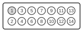
| Pin | Name |
|---|---|
| 1 | +5V |
| 2 | +5V |
| 3 | +5V |
| 4 | +5V |
| 5 | GND1 |
| 6 | GND2 |
| 7 | GND3 |
| 8 | GND4 |
| 9 | +12V |
| 10 | KEY |
| 11 | -12V |
| 12 | +5V USER |
| 13 | -5V |
| 14 | TICK |
Signals
- +5V (pins 1–4) — main +5 V supply rail; four pins are used in parallel to carry sufficient current to the motherboard logic.
- GND1–GND4 (pins 5–8) — ground return lines; four separate ground pins reduce resistance and allow adequate current return for all supply rails.
- +12V (pin 9) — positive 12 V rail, used by the floppy drive motor and other peripherals.
- KEY (pin 10) — this pin position is physically absent (missing pin) on the connector housing; it serves as a mechanical keying feature to ensure the cable is inserted in the correct orientation.
- -12V (pin 11) — negative 12 V rail.
- +5V USER (pin 12) — a secondary +5 V supply intended for user-installed expansion hardware; typically not present on standard PC ATX power supplies used as replacements.
- -5V (pin 13) — negative 5 V rail; also absent from most modern ATX power supplies, requiring a dedicated converter when using a non-original PSU.
- TICK (pin 14) — a 50 Hz or 60 Hz square wave derived from the mains frequency, used by the Amiga operating system for timing (the
CIABtimer). Standard PC power supplies do not provide this signal; when fitting a replacement PSU, the system must be configured to derive timing from the video VSYNC signal instead.
Notes
- The connector is a Molex 2139 KK series, 3.96 mm (0.156 in) pitch, 14-way single-row housing.
- Pin 10 (KEY) is a physically absent pin used solely for mechanical orientation; no electrical connection is made at this position.
- The TICK signal (pin 14) is unique to Amiga power connectors and is not present on standard ATX or AT power supplies. Replacement PSUs require a system-level workaround (e.g., using VSYNC as the timing source).
- The +5V USER rail (pin 12) and −5V rail (pin 13) are also absent from modern ATX power supplies; compatibility adaptors for the A2000 must either generate these rails or verify they are unused by the installed expansion cards.
- This is a fully internal connector; the A2000 houses its PSU internally and does not use an external power brick as the A500 does.