
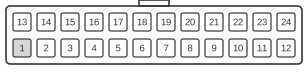
 24 pin MOLEX 44206-0007 connector at the System Board.
The HP Kayak workstation uses a proprietary 24-pin MOLEX 44206-0007 power connector that is physically and electrically incompatible with the standard ATX power connector despite sharing a similar pin count. The connector carries the standard DC voltage rails (+3.3 V, +5 V, +12 V, −5 V, −12 V, and a standby supply) but substitutes HP-proprietary control signals — including fan management lines — in place of certain ATX-standard signals. Later HP workstation families such as the xw4000 and xw6000 series continued this practice of replacing ATX-standard signals (PWR_OK, −12 V) with fan control signals (Fan OFF, Fan Cmd, Fan Sink), making commodity ATX power supplies unsuitable replacements in HP workstation-class systems of this era.
| System Board Pin | Name | Color | Description |
|---|---|---|---|
| 1 | PwrGood | blue | Power Ok (+5V & +3.3V is ok) |
| 2 | V_STBY | orange | Standby Voltage |
| 3 | +5V | red | |
| 4 | +5V | red | |
| 5 | +5V | red | |
| 6 | +5V | red | |
| 7 | +5V | red | |
| 8 | +3V | brown | |
| 9 | +3V | brown | |
| 10 | +3V | brown | |
| 11 | +3V | brown | |
| 12 | +3V | brown | |
| 13 | Remote On | white | Power Supply On |
| 14 | -5V | purple | |
| 15 | -12V | green | |
| 16 | +12V | yellow | |
| 17 | Ground | black | |
| 18 | Ground | black | |
| 19 | Ground | black | |
| 20 | Ground | black | |
| 21 | Ground | black | |
| 22 | Ground | black | |
| 23 | Ground | black | |
| 24 | Low Power | grey |
Notes
- The MOLEX 44206-0007 housing is keyed to prevent incorrect insertion; the connector is not mechanically interchangeable with a standard ATX 20-pin or 24-pin supply connector despite superficial similarity in pin count.
- Standard ATX power supplies must not be used as drop-in replacements: the signal assignments on several pins differ from ATX, and connecting an ATX supply may damage the system board or the supply.
- On subsequent HP workstation generations (xw4000/xw6000 series), the 24-pin proprietary connector replaces the ATX PWR_OK signal with a Fan OFF signal and uses a Fan Cmd line in place of the ATX −12 V rail, further diverging from the ATX specification.
- A separate 4-pin CPU/auxiliary power connector is used alongside the main connector on xw-series boards; the two connectors are not interchangeable with their ATX counterparts.
Signals
- PwrGood — asserted by the power supply to indicate that the +5 V and +3.3 V rails are within specification and stable; the system board holds the processor in reset until this signal is asserted.
- V_STBY — standby voltage rail (orange wire) that remains active whenever mains power is present, enabling wake-on-LAN and similar standby functions.
- +5V — main +5 V DC rail; distributed across multiple pins (3–7) to carry sufficient current for board logic and peripheral devices.
- +3V — main +3.3 V DC rail; distributed across multiple pins (8–12) for low-voltage logic.
- Remote On — active-low control signal (white wire) driven by the system board to command the power supply to switch on; equivalent in function to the ATX PS_ON# signal.
- -5V — negative 5 V rail, carried on pin 14 (purple wire); used by legacy ISA bus circuitry on this platform.
- -12V — negative 12 V rail, carried on pin 15 (green wire); used by RS-232 line drivers and similar circuitry.
- +12V — positive 12 V rail, carried on pin 16 (yellow wire); supplies motors, fans, and other higher-voltage loads.
- Ground — return path for all DC rails; distributed across pins 17–23 to minimise resistive losses at high currents.
- Low Power — HP-proprietary signal on pin 24 (grey wire); function is platform-specific and may relate to a reduced-power or sleep state command from the system board to the power supply.