
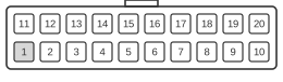
 20 pin MOLEX 39-29-9202 connector at the motherboard.
The SFX (Small Form Factor) 20-pin main power connector shares the same Molex Mini-Fit Jr. housing and pin assignments as the ATX 20-pin connector, governed by Intel’s ATX and SFX/SFX12V Power Supply Design Guides. It was introduced alongside the SFX form factor to supply compact desktop and small form-factor PCs from the late 1990s onward with +3.3 V, +5 V, +12 V, and −12 V rails alongside the always-on +5VSB standby. The sole difference from ATX v2.03 is that pin 18, which carried the optional −5 V rail in older ATX revisions, is left Reserved (no connection) in SFX.
| Color | Pin | Name | Description | Color | Pin | Name | Description | |
|---|---|---|---|---|---|---|---|---|
| orange | 1 | +3.3 VDC | Power +3.3V | orange | 11 | +3.3 VDC | Power +3.3V | |
| orange | 2 | +3.3 VDC | Power +3.3V | blue | 12 | -12 VDC | Power -12V | |
| black | 3 | GND | Ground | black | 13 | GND | Ground | |
| red | 4 | +5 VDC | Power +5V | green | 14 | PS-ON | Remote Power ON/OFF | |
| black | 5 | GND | Ground | black | 15 | GND | Ground | |
| red | 6 | +5 VDC | Power +5V | black | 16 | GND | Ground | |
| black | 7 | GND | Ground | black | 17 | GND | Ground | |
| grey | 8 | PWROK | Power Good | 18 | Reserved | |||
| purple | 9 | +5 VSB | +5V Standby | red | 19 | +5 VDC | Power +5V | |
| yellow | 10 | +12 VDC | Power +12V | red | 20 | +5 VDC | Power +5V |
Signals
- +3.3 VDC — 3.3 V supply rail (pins 1, 2, 11); tolerance ±5% (3.14–3.47 V); orange wires. Pin 11 acts as a sense return and should use a 22 AWG wire.
- +5 VDC — 5 V supply rail (pins 4, 6, 19, 20); tolerance ±5% (4.75–5.25 V); red wires.
- GND — Common ground return (pins 3, 5, 7, 13, 15, 16, 17); black wires.
- PWROK — Power Good signal; +5 V TTL-compatible logic high (2.4–5 V) asserted 100–500 ms after PS-ON# activates, indicating rails are within regulation. Drops at least 1 ms before any rail falls out of tolerance. Grey wire.
- +5 VSB — +5 V standby rail (pin 9); remains live whenever AC mains power is present, regardless of PS-ON# state; supports soft power control and wake functions. Purple wire; tolerance ±5%.
- +12 VDC — 12 V supply rail (pin 10); tolerance ±5% (11.40–12.60 V); yellow wire.
- PS-ON — Active-low TTL-compatible remote power enable (pin 14); PSU provides internal pull-up to ≤5.25 V. Pulling low enables all main rails (+12 V, +5 V, +3.3 V, −12 V). Green wire; VIL 0–0.8 V, VIH ≥2.0 V.
- −12 VDC — −12 V supply rail (pin 12); tolerance ±10% (−10.80 to −13.20 V); used primarily for legacy RS-232 transceivers. Blue wire.
- Reserved — Pin 18 carries no connection in SFX; the −5 V rail that occupied this pin in ATX v2.03 and earlier was removed.
Notes
- Pin assignments are identical to ATX except that pin 18 is Reserved (no connection) in SFX, rather than carrying the −5 V rail present in ATX v2.03 and older.
- The connector body is a Molex Mini-Fit Jr. dual-row housing (4.20 mm pitch); keying prevents reversal but does not prevent mis-mating with other housings of different pin counts.
- The SFX power connector on the motherboard consists of two rows of 10 pins; this connector can only be inserted in one orientation.
- PS-ON is activated by pressing the power button, which pulls the green wire to ground and switches the supply from standby to full-on.
- 18 AWG wire is recommended for all pins except pin 11 (+3.3 V sense), which should use 22 AWG.
- For 300 W configurations, 16 AWG wire is recommended.
- Voltage tolerances: +12 V ±5%, +5 V ±5%, +3.3 V ±5%, −12 V ±10%, +5VSB ±5%.
- The SFX form factor specifies a smaller PSU chassis (typically 125 mm W × 100 mm D × 63.5 mm H) than full ATX, but the electrical connector and pin assignments remain compatible.
References
- ATX12V Power Supply Design Guide Version 1.3 (Intel, April 2003)
- ATX Version 3.0 Multi Rail Desktop Platform Power Supply Design Guide v2.01 — Main Power Connector (Intel)
- ATX Version 3.0 Multi Rail Desktop Platform Power Supply Design Guide v2.01 — PS_ON# (Intel)
- ATX Specification Version 2.01 (Intel, February 1997)