
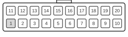
 ATX ver. 1.x 20 pin connector at the power supply cable
ATX ver. 1.x 20 pin MOLEX 39-29-9202 connector at the motherboard
The ATX 20-pin main power connector replaced the earlier AT-era P8/P9 split connectors and was standardised by Intel with the ATX Specification v1.1 in 1996, remaining the dominant desktop motherboard power interface through the ATX12V v1.x era. It uses a Molex Mini-Fit Jr. 4.20 mm-pitch dual-row housing (cable receptacle Molex 39-01-2200; board header Molex 39-29-9202) that is keyed to prevent reversal. In addition to the +5 V and +12 V rails inherited from AT power, ATX introduced the +3.3 V supply rail, a +5VSB always-on standby voltage, the active-low PS_ON# soft power-control signal, and the PWR_OK Power Good signal. The version 1.x connector carries a −5 V rail on pin 18, which became optional from ATX12V v1.2 onward and was removed entirely in ATX12V v1.3.
| Color | Pin | Name | Description | Color | Pin | Name | Description | |
|---|---|---|---|---|---|---|---|---|
| orange | 1 | +3.3 VDC | Power +3.3V | brown | 11 | +3.3 VDC | Power +3.3V | |
| orange | 2 | +3.3 VDC | Power +3.3V | blue | 12 | -12 VDC | Power -12V | |
| black | 3 | GND | Ground | black | 13 | GND | Ground | |
| red | 4 | +5 VDC | Power +5V | green | 14 | PS-ON | Remote Power ON/OFF | |
| black | 5 | GND | Ground | black | 15 | GND | Ground | |
| red | 6 | +5 VDC | Power +5V | black | 16 | GND | Ground | |
| black | 7 | GND | Ground | black | 17 | GND | Ground | |
| grey | 8 | PWROK | Power Good | white | 18 | -5V | Power -5V | |
| purple | 9 | +5 VSB | +5V Standby | red | 19 | +5 VDC | Power +5V | |
| yellow | 10 | +12 VDC | Power +12V | red | 20 | +5 VDC | Power +5V |
Notes
- The Molex Mini-Fit Jr. housing is keyed and asymmetric, so the cable connector can only be inserted in one orientation; however, it does not prevent accidental mating with a different-pinned housing of the same family.
- PS_ON# is pulled low by the motherboard power button circuit to switch the PSU from standby to full-on; the PSU provides an internal pull-up to keep the line at TTL high when open.
- +5VSB (pin 9) remains live whenever mains AC is present, regardless of the PS_ON# state, enabling standby functions such as Wake-on-LAN.
- PWR_OK asserts high 100–500 ms after PS_ON# is activated and drops at least 1 ms before the output rails fall out of regulation, giving the CPU time to initiate a clean shutdown sequence.
- 18 AWG is specified for all wires except pin 11 (+3.3 V sense), which uses 22 AWG. 16 AWG is recommended for 300 W configurations.
- Pin 18 (−5 V) is present on v1.x connectors but was made optional from ATX12V v1.2 and removed in ATX12V v1.3; ATX12V v2.x 24-pin supplies typically do not provide this rail.
- Voltage regulation tolerances: +12 V ±5% (11.40–12.60 V), +5 V ±5% (4.75–5.25 V), +3.3 V ±5% (3.14–3.47 V), −12 V ±10% (−10.80 to −13.20 V), +5VSB ±5% (4.75–5.25 V).
Connector part numbers
- Motherboard connector: Molex 39-29-9202
- Cable connector: Molex 39-01-2200
- Terminals: Molex 39-00-0168, Molex 44476-1111
- Maximum current per circuit: 9 A (Mini-Fit Jr. contact rating)
Signals
- +3.3 VDC — 3.3 V supply rail (orange); introduced with ATX to power logic circuits directly without on-board regulation; present on pins 1, 2.
- +3.3 VDC sense — Remote-sense return for the +3.3 V rail (brown, 22 AWG); pin 11 only; allows the PSU to compensate for cable voltage drop and must not be confused with the supply pins.
- +5 VDC — 5 V supply rail (red); primary logic supply for ISA/PCI devices; pins 4, 6, 19, 20.
- +12 VDC — 12 V supply rail (yellow); powers motors and, in later platforms, the CPU VRM; pin 10.
- −12 VDC — Negative 12 V rail (blue); used by RS-232 serial port transceivers; low-current supply; pin 12.
- −5 VDC — Negative 5 V rail (white); pin 18; legacy rail for ISA bus; optional from ATX12V v1.2, removed in ATX12V v1.3.
- +5VSB — Always-on +5 V standby rail (purple); pin 9; active whenever AC power is present; supports Wake-on-LAN, RTC, and keyboard power-on functions.
- PS_ON# — Active-low PSU enable signal (green); pin 14; pulling to TTL low (0–0.8 V) enables all main rails; PSU holds pin high (up to 5.25 V) via internal pull-up when open.
- PWR_OK — Power Good signal (grey); pin 8; +5 V TTL-compatible output; asserts high (2.4–5 V) 100–500 ms after rails are within regulation; used by the motherboard to release the CPU reset.
- GND — Ground return (black); pins 3, 5, 7, 13, 15, 16, 17.