
The Olivetti M10 (1983) is a portable computer built on the Kyocera hardware platform, which it shares with the Tandy TRS-80 Model 100, Tandy 102/200/600, NEC PC-8201A/PC-8300, and Kyotronic KC-85; these machines use identical printer port hardware and the same cables are interchangeable between them. The printer interface uses a 26-pin IDC (ribbon cable) male connector and conforms functionally to the Centronics parallel standard via an adapter cable. Eight data bits are driven through the PA0–PA7 port lines of an 81C55 PIO chip, with a two-signal handshake: the host asserts /STROBE (active-low pulse) after placing data on D0–D7, and the printer raises BUSY while processing; the host must wait for BUSY to deassert before sending the next byte. TTL-level signals are used throughout.
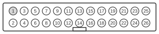 26 PIN IDC MALE at the Computer
| Pin | Name | Dir | Description |
|---|---|---|---|
| 1 | /STROBE | OUT | Strobe |
| 2 | D0 | OUT | Data Bit 0 |
| 3 | D1 | OUT | Data Bit 1 |
| 4 | D2 | OUT | Data Bit 2 |
| 5 | D3 | OUT | Data Bit 3 |
| 6 | D4 | OUT | Data Bit 4 |
| 7 | D5 | OUT | Data Bit 5 |
| 8 | D6 | OUT | Data Bit 6 |
| 9 | D7 | OUT | Data Bit 7 |
| 10 | /ACK | IN | Acknowledge |
| 11 | BUSY | IN | Busy |
| 12 | PE | IN | Paper End |
| 13 | SELIN | IN | Select In |
| 14 | GND | - | Signal Ground |
| 15 | GND | - | Signal Ground |
| 16 | GND | - | Signal Ground |
| 17 | GND | - | Signal Ground |
| 18 | GND | - | Signal Ground |
| 19 | GND | - | Signal Ground |
| 20 | GND | - | Signal Ground |
| 21 | GND | - | Signal Ground |
| 22 | GND | - | Signal Ground |
| 23 | GND | - | Signal Ground |
| 24 | GND | - | Signal Ground |
| 25 | RESETGND | - | Reset Ground |
| 26 | /RESET | IN | Reset |
Notes
- Direction is Computer relative Device.
- The connector is a 26-pin IDC (flat ribbon cable) male header, not a standard Centronics socket; a dedicated adapter cable is required to connect to Centronics-compatible printers.
- The Olivetti M10, Tandy TRS-80 Model 100, Tandy 102/200/600, NEC PC-8201A/PC-8300, and Kyotronic KC-85 all share the same Kyocera hardware platform; printer cables and adapters are interchangeable across the family.
- /STROBE is driven via a transistor output (active-low); the printer interface I/O port address range is E0H–EFH.
Signals
- D0–D7 — 8-bit parallel data output lines, driven through the PA0–PA7 port of the 81C55 PIO chip; TTL level.
- /STROBE — active-low strobe output; asserted by the host after data is stable on D0–D7 to signal the printer to latch the byte.
- /ACK — active-low acknowledge input from the printer; indicates the byte has been received.
- BUSY — input from the printer; held high while the printer is processing a byte; the host must wait for BUSY to return low before sending the next byte.
- PE — paper-end input; high when the printer is out of paper.
- SELIN — select-in input; indicates printer selected state.
- /RESET — reset input; function relative to the printer device.
- GND — signal ground (pins 14–24).
- RESETGND — reset ground reference (pin 25).
References
- TRS-80 Model 100 Technical Reference Manual — Tandy Corporation, 1984