
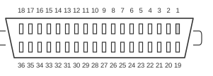
 36 pin CENTRONICS female connector at the printer.
The IEEE 1284-B connector is the 36-pin, 0.085-inch pitch Centronics-style plug defined by IEEE 1284-2000 (first ratified as IEEE 1284-1994) for use on the peripheral — typically printer — end of a parallel cable. It carries the same 17 signal lines as the Type A DB-25 host connector: eight data lines, four control outputs from the host, and five status inputs from the peripheral, along with signal returns and power. The standard permits a maximum cable length of 25 feet and specifies a cable characteristic impedance of 62 ± 6 ohms. Pins 33–36 are unassigned in the IEEE 1284-B definition and are typically left unconnected.
| Pin | Description | Signal | Source |
|---|---|---|---|
| 1 | Data Strobe (low) | STROBE | Computer |
| 2 | Data Bit 1 (LSB) | D1 | Computer |
| 3 | Data Bit 2 | D2 | Computer |
| 4 | Data Bit 3 | D3 | Computer |
| 5 | Data Bit 4 | D4 | Computer |
| 6 | Data Bit 5 | D5 | Computer |
| 7 | Data Bit 6 | D6 | Computer |
| 8 | Data Bit 7 | D7 | Computer |
| 9 | Data Bit 8 (LSB) | D8 | Computer |
| 10 | Acknowledge (low) | ACK | Printer |
| 11 | Busy (high) | BUSY | Printer |
| 12 | Paper End (high) | PE | Printer |
| 13 | Select (high) | SEL | Printer |
| 14 | Supply Ground | - | |
| 15 | Oscillator Transmit | Printer | |
| 16 | Logical Ground | - | |
| 17 | Chassis Ground | - | |
| 18 | +5 Vdc | +V | Printer |
| 19 | Return Data Strobe | - | |
| 20 | Return Data Bit 1 | - | |
| 21 | Return Data Bit 2 | - | |
| 22 | Return Data Bit 3 | - | |
| 23 | Return Data Bit 4 | - | |
| 24 | Return Data Bit 5 | - | |
| 25 | Return Data Bit 6 | - | |
| 26 | Return Data Bit 7 | - | |
| 27 | Return Data Bit 8 | - | |
| 28 | Return ACK | - | |
| 29 | Return BUSY | - | |
| 30 | Return Input Prime | - | |
| 31 | Input Prime (low) | Computer | |
| 32 | Fault (low) | FAULT | Printer |
| 33 | - | - | - |
| 34 | - | - | - |
| 35 | - | - | - |
| 36 | - | - | - |
Notes
The 1284-B connector uses 0.085-inch pitch and is mechanically equivalent to the original Centronics 36-pin interface used on parallel printers since the 1970s; IEEE 1284 formalised its electrical and signalling requirements. The companion 1284-C connector uses a smaller 0.050-inch pitch (half-pitch MDR-36) and can serve both host and peripheral ends. Level II electrical specification (required for IEEE 1284 compliance): driver output VOH ≥ 2.4 V at 14 mA source current; VOL ≤ 0.4 V at 14 mA sink current; output impedance 50 ± 5 ohms; slew rate 0.05–0.40 V/ns. Receiver thresholds: VIH ≤ 2.0 V, VIL ≥ 0.8 V, hysteresis 0.2–1.2 V. Host and peripheral capability are negotiated via the IEEE 1284 negotiation sequence. Pins 33–36 are unassigned in the IEEE 1284-B definition.
Signals
- STROBE — Active-low pulse from the host used to clock data into the printer; pulse width must be between 0.5 and 500 microseconds for most printers.
- D1–D8 — Eight bidirectional data lines carrying one byte per transfer cycle.
- ACK — Active-low pulse from the printer indicating that data has been received and the printer is ready to accept more.
- BUSY — High signal from the printer indicating it cannot accept further data.
- PE — High signal from the printer indicating a paper-out condition.
- SEL — High signal from the printer indicating it is on-line and selected.
- OSCXT — 100–200 kHz oscillator signal used by original Centronics printers only; not implemented by most later printers.
- +5V — +5 Vdc supply; not provided by all manufacturers.
- PRIME (nINIT) — Active-low signal from the host that resets the printer to its power-up state and clears the print buffer.
- FAULT — Active-low signal from the printer indicating an off-line or error condition.
- Host Logic High — IEEE 1284-specific signal indicating that the host is powered on; not present on the 1284-A (DB-25) connector.
- Peripheral Logic High — IEEE 1284-specific signal indicating that the peripheral is powered on; not present on the 1284-A connector.
References
- IEEE 1284-2000 — IEEE Standard Signaling Method for a Bidirectional Parallel Peripheral Interface for Personal Computers
- IEEE 1284-1994 — IEEE Standard Signaling Method for a Bidirectional Parallel Peripheral Interface for Personal Computers (superseded)
- The IEEE 1284-1994 Standard (Parallel Port) — MCABase Technical Reference