
The Extended Capabilities Port (ECP) is a high-performance, fully bidirectional parallel interface developed by Hewlett-Packard and Microsoft, first published in November 1992 and subsequently incorporated into the IEEE 1284-1994 standard (revised as IEEE 1284-2000). It operates over the same 25-pin DB-25 (IEEE 1284 Type A) connector used by the Standard Parallel Port, sharing its 17 signal lines but reassigning them with distinct ECP names and handshake semantics. ECP is DMA-driven — typically using ISA DMA channel 3 — to offload the host CPU, and it supports run-length encoding (RLE) compression with a maximum ratio of 64:1 for long runs of repeated bytes. A channel-addressing scheme allows up to 128 logical devices or channels to share a single physical port, with a command byte on the data lines selecting the active channel.
ECP Hardware Properties
 (25 PIN D-SUB FEMALE at the PC)
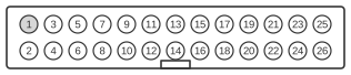 (26 Pin MALE connector on the mainboard)
While Extended Capabilities Ports use exactly the same DB-25 connector as the Standard Parallel Port, ECP assigns different names and functions to each pin. The port is backwards compatible with SPP and EPP: when negotiated into SPP mode the lines behave as Strobe, Auto Linefeed, Init, Busy, and so forth; when negotiated into ECP mode, the following ECP signal names and handshake protocol apply.
(26 Pin MALE connector on the mainboard)
While Extended Capabilities Ports use exactly the same DB-25 connector as the Standard Parallel Port, ECP assigns different names and functions to each pin. The port is backwards compatible with SPP and EPP: when negotiated into SPP mode the lines behave as Strobe, Auto Linefeed, Init, Busy, and so forth; when negotiated into ECP mode, the following ECP signal names and handshake protocol apply.
| Pin | SPP Signal | ECP Signal | IN/OUT | Function |
|---|---|---|---|---|
| 1 | Strobe | HostCLK | Out | A low on this line indicates, that there is valid data at the host. When this pin is de-asserted, the +ve clock edge should be used to shift the data into the device. |
| 2 | data0 | data0 | IN/OUT | Address, Data or RLE Data Bit 0 |
| 3 | data1 | data1 | IN/OUT | Address, Data or RLE Data Bit 1 |
| 4 | data2 | data2 | IN/OUT | Address, Data or RLE Data Bit 2 |
| 5 | data3 | data3 | IN/OUT | Address, Data or RLE Data Bit 3 |
| 6 | data4 | data4 | IN/OUT | Address, Data or RLE Data Bit 4 |
| 7 | data5 | data5 | IN/OUT | Address, Data or RLE Data Bit 5 |
| 8 | data6 | data6 | IN/OUT | Address, Data or RLE Data Bit 6 |
| 9 | data7 | data7 | IN/OUT | Address, Data or RLE Data Bit 7 |
| 10 | Ack | PeriphCLK | In | A low on this line indicates, that there is valid data at the Device. When this pin is de-asserted, the +ve clock edge should be used to shift the data into the Host. |
| 11 | Busy | PeriphAck | In | When in reverse direction a HIGH indicates Data, while a LOW indicates a Command Cycle. In forward direction, functions as PeriphAck. |
| 12 | Paper Out / End | nAckReverse | In | When Low, Device acknowledges Reverse Request. |
| 13 | Select | X-Flag | In | Extensibility Flag |
| 14 | Auto Linefeed | Host Ack | Out | When in forward direction a HIGH indicates Data, while a LOW indicates a Command Cycle. In reverse direction, functions as HostAck. |
| 15 | Error / Fault | PeriphRequest | In | A LOW set by the device indicates reverse data is available |
| 16 | Initialize | nReverseRequest | Out | A LOW indicates data is in reverse direction |
| 17 | Select Printer | 1284 Active | Out | A HIGH indicates Host is in 1284 Transfer Mode. Taken low to terminate. |
| 18 | GND | GND | - | Signal Ground |
| 19 | GND | GND | - | Signal Ground |
| 20 | GND | GND | - | Signal Ground |
| 21 | GND | GND | - | Signal Ground |
| 22 | GND | GND | - | Signal Ground |
| 23 | GND | GND | - | Signal Ground |
| 24 | GND | GND | - | Signal Ground |
| 25 | GND | GND | - | Signal Ground |
Table 1. Pin Assignments For Extended Capabilities Parallel Port Connector. The HostAck and PeriphAck lines indicate whether the signals on the data line are data or a command. If these lines are high then data is placed on the data lines (Pins 2-7). If a command cycle is taking place then the appropriate line will be low, ie if the host is sending a command, then HostAck will be low or if the device/peripheral is sending a command the PeriphAck line will be low. A command cycle can be one of two things, either a RLE count or an address. This is determined by the bit 7 (MSB) of the data lines, ie Pin 9. If bit 7 is a 0, then the rest of the data (bits 0-6) is a run length count which is used with the data compression scheme. However if bit 7 is a 1, then the data present on bits 0 to 6 is a channel address. With one bit missing this can only be a value from 0 to 127(DEC). Note: Direction is Computer relative Device.
Signals
- HostClk (pin 1, ECP name for SPP nStrobe) — driven low by the host to indicate valid data or command on the data lines; the peripheral latches on the rising edge.
- data0–data7 (pins 2–9) — bidirectional address, data, or RLE data lines; carry channel-address commands or run-length counts when HostAck or PeriphAck is low.
- PeriphClk (pin 10, ECP name for SPP nAck) — driven low by the peripheral to indicate valid reverse data; host latches on the rising edge.
- PeriphAck (pin 11, ECP name for SPP Busy) — high in data cycle, low in command cycle when peripheral is sending; also functions as the reverse-direction handshake with HostClk.
- nAckReverse (pin 12, ECP name for SPP PError) — driven low by the peripheral to acknowledge the host’s nReverseRequest.
- Xflag / X-Flag (pin 13, ECP name for SPP Select) — extensibility flag; meaning is negotiated between host and peripheral.
- HostAck (pin 14, ECP name for SPP nAutoFd) — high in data cycle, low in command cycle when host is sending; also functions as the forward-direction handshake with PeriphClk.
- nPeriphRequest (pin 15, ECP name for SPP nFault) — asserted low by peripheral to indicate that reverse data is available.
- nReverseRequest (pin 16, ECP name for SPP nInit) — asserted low by host to request a transfer direction change to reverse (peripheral-to-host).
- 1284Active (pin 17, ECP name for SPP nSelectIn) — driven high by host while in IEEE 1284 transfer mode; taken low to terminate.
- GND (pins 18–25) — signal ground returns.
Notes
- The Configuration Register B (cnfgB) can be a combination of read/write access. Some ports may be software configurable, where you can set the IRQ and DMA resources from the register. Others may be set via BIOS or by using jumpers on the Card, thus are read only.
- Bit 7 of the cnfgB Register selects whether to compress outgoing data using RLE (Run Length Encoding.) When Set, the host will compress the data before sending. When reset, data will be sent to the peripheral raw (Uncompressed). Bit 6 returns the status of the IRQ pin. This can be used to diagnose conflicts as it will not only reflect the status of the Parallel Ports IRQ, but and other device using this IRQ.
- Bits 5 to 3 give status of about the Port’s IRQ assignment. Likewise for bits 2 to 0 which give status of DMA Channel assignment. As mentioned above these fields may be read/write. The disappearing species of Parallel Cards which have Jumpers may simply show its resources as “Jumpered” or it may show the correct Line Numbers. However these of course will be read only.
References
- IEEE 1284-2000 — IEEE Standard Signaling Method for a Bidirectional Parallel Peripheral Interface for Personal Computers
- IEEE 1284-1994 — IEEE Standard Signaling Method for a Bidirectional Parallel Peripheral Interface for Personal Computers (superseded)
- IEEE 1284 ECP Mode — Signal Mapping and Protocol (ps-2.kev009.com)
- The IEEE 1284-1994 Standard — MCABase Technical Reference (ps-2.kev009.com)