
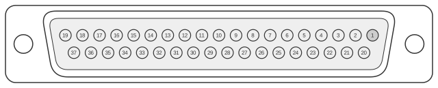
 37 pin D-SUB female connector at the computer.
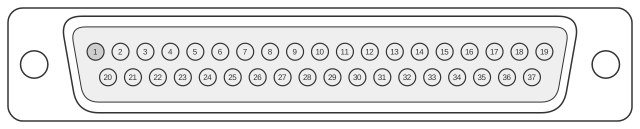 37 pin D-SUB male connector at the cable.
The DC-37 (37-pin D-sub) connector appears on the host or controller side of the Dataproducts-compatible parallel interface used by Digital Equipment Corporation’s LP-series line printer controllers. On UNIBUS-based PDP-11 systems the LP11 controller (modules M7930 and its successor M7258) presents a female DC-37 at the rear panel; on Q-bus systems the LPV11 performs the equivalent role. The BC27A shielded cable connects this 37-pin female socket to the 50-pin male D-sub (DD-50) on the printer, and was used with the LP25, LP26, LP27, and LP32 Dataproducts-protocol printers. The interface carries seven parallel data lines, a Paper Instruction channel for vertical format control, a Data Strobe from host to printer, and a Demand handshake line from printer to host — a distinct signalling scheme from the contemporary Centronics parallel standard.
| Pin | Name | Dir | Description |
|---|---|---|---|
| 1 | DAT<3> | OUT | Data Bit 3 |
| 2 | Not available | ||
| 3 | Not available | ||
| 4 | Not available | ||
| 5 | DAT<6> | OUT | Data Bit 6 |
| 6 | DAT<7> | OUT | Data Bit 7 |
| 7 | Not available | ||
| 8 | Strobe | OUT | Data Bit 1 |
| 9 | Not available | ||
| 10 | Not available | ||
| 11 | Not available | ||
| 12 | On Line | IN | Strobe |
| 13 | Not available | ||
| 14 | Connection | OUT | Connection |
| 15 | Not available | ||
| 16 | Not available | ||
| 17 | DAVFU | OUT | DAVFU |
| 18 | Demand | IN | Data Bit 0 |
| 19 | Not available | ||
| 20 | DAT<1> | OUT | Data Bit 2 |
| 21 | Not available | ||
| 22 | DAT<2> | OUT | Data Bit 2 |
| 23 | DAT<4> | OUT | Data Bit 4 |
| 24 | DAT<5> | OUT | Data Bit 5 |
| 25 | Not available | ||
| 26 | DAT<0> | OUT | Data Bit 2 |
| 27 | Ground | - | Ground |
| 28 | Ground DAT<0> | - | Ground Data Bit 0 |
| 29 | Ground DAT<1> | - | Ground Data Bit 1 |
| 30 | Ground DAT<2> | - | Ground Data Bit 2 |
| 31 | Ground DAT<3> | - | Ground Data Bit 3 |
| 32 | Ground DAT<4> | - | Ground Data Bit 4 |
| 33 | Ground DAT<5> | - | Ground Data Bit 5 |
| 34 | Ground DAT<6> | - | Ground Data Bit 6 |
| 35 | Ground DAT<7> | - | Ground Data Bit 7 |
| 36 | Not available | ||
| 37 | Not available |
Notes
The 37-pin D-sub here is the controller (host) end of the Dataproducts short-line parallel interface. The corresponding printer end uses a 50-pin D-sub (DD-50), connected via the BC27A cable (9.2 m / 30 ft or 15.2 m / 50 ft versions). The interface uses single-ended (unbalanced) TTL signalling; the maximum recommended cable length is approximately 40–50 feet. Each signal line has a dedicated return/ground pair (pins 28–35 carry the ground returns for the eight data lines). The DAVFU (pin 17) carries the Dataproducts Vertical Format Unit signal used to control paper positioning. Pins 2–4, 7, 9–11, 13, 15–16, 19, 21, 25, 36–37 are listed as not available in the documented connector configuration.
Signals
- DAT<0>–DAT<6> — Seven parallel data lines from host to printer, TTL levels, carrying character data one byte per strobe cycle.
- Strobe — Data Strobe from host to printer; high-true pulse that clocks the parallel data into the printer.
- Demand — Handshake signal from printer to host; high-true, indicates the printer is ready to accept the next character. This replaces the ACKNOWLEDGE/BUSY scheme used by the Centronics interface.
- On Line — Status signal from printer to host; high-true when the printer has power, paper loaded, and the operator has activated the Online switch.
- Connection — Interface verification signal; function is a loopback or continuity check at the printer end (pin 14).
- DAVFU — Dataproducts Vertical Format Unit channel, carrying paper-motion control instructions with the same timing and polarity as the data lines.
- Ground DAT<0>–DAT<7> — Individual signal-return (ground) lines paired with each data channel (pins 28–35).
- Ground — Common ground reference (pin 27).