
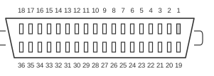
 36 PIN CENTRONICS FEMALE at the Printer
The Centronics parallel interface is an 8-bit parallel port developed by the printer manufacturer Centronics around 1970 and quickly adopted as the de-facto way to connect printers to personal computers. The printer end uses a 36-pin Centronics (Amphenol “micro-ribbon”) connector, while the computer end typically uses a 25-pin D-sub (DB-25), so a standard printer cable has a different connector at each end. Data is sent one byte at a time over eight data lines, coordinated by handshake signals such as STROBE, BUSY and ACK at TTL (0–5 V) logic levels. The interface was later formalised as the IEEE 1284 standard (1994), which added faster bidirectional modes (EPP and ECP); the original Centronics design was unidirectional, from the computer to the printer.
| Pin | Name | Dir | Description |
|---|---|---|---|
| 1 | /STROBE | IN | Strobe |
| 2 | D0 | IN/OUT | Data Bit 0 |
| 3 | D1 | IN/OUT | Data Bit 1 |
| 4 | D2 | IN/OUT | Data Bit 2 |
| 5 | D3 | IN/OUT | Data Bit 3 |
| 6 | D4 | IN/OUT | Data Bit 4 |
| 7 | D5 | IN/OUT | Data Bit 5 |
| 8 | D6 | IN/OUT | Data Bit 6 |
| 9 | D7 | IN/OUT | Data Bit 7 |
| 10 | /ACK | OUT | Acknowledge |
| 11 | BUSY | OUT | Busy |
| 12 | POUT | OUT | Paper Out |
| 13 | SEL | OUT | Select |
| 14 | /AUTOFEED | IN | Autofeed |
| 15 | n/c | - | Not used |
| 16 | 0 V | —— | Logic Ground |
| 17 | CHASSIS GND | —— | Shield Ground |
| 18 | +5 V PULLUP | OUT | +5 V DC (50 mA max) |
| 19 | GND | —— | Signal Ground (Strobe Ground) |
| 20 | GND | —— | Signal Ground (Data 0 Ground) |
| 21 | GND | —— | Signal Ground (Data 1 Ground) |
| 22 | GND | —— | Signal Ground (Data 2 Ground) |
| 23 | GND | —— | Signal Ground (Data 3 Ground) |
| 24 | GND | —— | Signal Ground (Data 4 Ground) |
| 25 | GND | —— | Signal Ground (Data 5 Ground) |
| 26 | GND | —— | Signal Ground (Data 6 Ground) |
| 27 | GND | —— | Signal Ground (Data 7 Ground) |
| 28 | GND | —— | Signal Ground (Acknowledge Ground) |
| 29 | GND | —— | Signal Ground (Busy Ground) |
| 30 | /GNDRESET | —— | Reset Ground |
| 31 | /RESET | IN | Reset |
| 32 | /FAULT | OUT | Fault (Low when offline) |
| 33 | 0 V | —— | Signal Ground |
| 34 | n/c | - | Not used |
| 35 | +5 V | OUT | +5 V DC |
| 36 | /SLCT IN | IN | Select In (Taking low or high sets printer on line or off line respectively) |
Notes
- In the pin table above, the Direction column is given relative to the printer: IN is a signal driven into the printer (by the computer), OUT is a signal the printer drives back to the computer.
- All signals use TTL logic levels (0–5 V).
- Practical cable length is short — generally up to about 25 ft (a few metres); longer runs become unreliable.
Signals
- STROBE — active-low, driven by the computer. Indicates that the byte on D0–D7 is valid and ready to be latched by the printer.
- D0–D7 — the data byte sent to the printer. Output-only from the computer in the original “compatible” mode, and bidirectional in the later IEEE 1284 modes.
- ACK (Acknowledge) — active-low, driven by the printer. Pulsed to confirm a byte has been received and the printer is ready for the next one.
- BUSY — active-high, driven by the printer. Held high while the printer is busy or its buffer is full; the computer must wait for it to return low before sending more data.
- PE (Paper End) — active-high, driven by the printer. The printer is out of paper.
- SLCT (Select) — active-high, driven by the printer. The printer is on line and ready.
- AUTO-FEED — active-low, driven by the computer. Requests an automatic line feed after each carriage return.
- ERROR (Fault) — active-low, driven by the printer. The printer has detected an error.
- INIT (Reset) — active-low, driven by the computer. Resets and initialises the printer.
- SLCT IN (Select In) — active-low, driven by the computer. Selects the printer on or off line.