
SPP = Standard Parallel Port
This is the original parallel port, it’s been used on all PC computers since the very beginning and has mostly remained unchanged over the years. When IBM came up with the first PC, they opted to go along the lines of the the most prominent printer manufacturer at the time, Centronics. This printer manufacturer had developed a set of control signals that was up to the task of controlling computer printers and since many printer manufacturers had been adopting this now standard design, it was the obvious choice to make. But when IBM constructed it’s PC they opted to not use the true Centronics connector which was a 36 conductor Amphenol connector (also known as the Centronics connector). IBM opted for a 25 pin D shell connector also called a DB-25 connector. Since then, printer manufacturers have always used Centronics connectors and PC manufacturers have been using DB-25 connectors. This is the reason why you need this special adapter cable that is known as a printer cable and is now a standard accessory. The Parallel Port is the most commonly used port for interfacing home made projects. This port will allow the input of up to 9 bits or the output of 12 bits at any one given time, thus requiring minimal external circuitry to implement many simpler tasks. The port is composed of 4 control lines, 5 status lines and 8 data lines. It’s found commonly on the back of your PC as a D-Type 25 Pin female connector. There may also be a D-Type 25 pin male connector. This will be a serial RS-232 port and thus, is a totally incompatible port. Newer Parallel Port’s are standardized under the IEEE 1284 standard first released in 1994. This standard defines 5 modes of operation which are as follows,
- Compatibility Mode.
- Nibble Mode. (Protocol not Described in this Document)
- Byte Mode. (Protocol not Described in this Document)
- EPP Mode (Enhanced Parallel Port)
- ECP Mode (Extended Capabilities Mode)
The aim was to design new drivers and devices which were compatible with each other and also backwards compatible with the Standard Parallel Port (SPP). Compatibility, Nibble & Byte modes use just the standard hardware available on the original Parallel Port cards while EPP & ECP modes require additional hardware which can run at faster speeds, while still being downwards compatible with the Standard Parallel Port. Compatibility mode or “Centronics Mode” as it is commonly known, can only send data in the forward direction at a typical speed of 50 kbytes per second but can be as high as 150+ kbytes a second. In order to receive data, you must change the mode to either Nibble or Byte mode. Nibble mode can input a nibble (4 bits) in the reverse direction. E.g. from device to computer. Byte mode uses the Parallel’s bi-directional feature (found only on some cards) to input a byte (8 bits) of data in the reverse direction. Extended and Enhanced Parallel Ports use additional hardware to generate and manage handshaking. To output a byte to a printer (or anything in that matter) using compatibility mode, the software must,
- Write the byte to the Data Port
- Check to see is the printer is busy. If the printer is busy, it will not accept any data, thus any data which is written will be lost
- Take the Strobe (Pin 1) low. This tells the printer that there is the correct data on the data lines. (Pins 2-9)
- Put the strobe high again after waiting approximately 5 microseconds after putting the strobe low. (Step 3)
This limits the speed at which the port can run at. The EPP & ECP ports get around this by letting the hardware check to see if the printer is busy and generate a strobe and /or appropriate handshaking. This means only one I/O instruction need to be performed, thus increasing the speed. These ports can output at around 1-2 megabytes per second. The ECP port also has the advantage of using DMA channels and FIFO buffers, thus data can be shifted around without using I/O instructions.
Hardware Properties
Below is a table of the “Pin Outs” of the D-Type 25 Pin connector and the Centronics 34 Pin connector. The D-Type 25 pin connector is the most common connector found on the Parallel Port of the computer, while the Centronics Connector is commonly found on printers. The IEEE 1284 standard however specifies 3 different connectors for use with the Parallel Port. The first one, 1284 Type A is the D-Type 25 connector found on the back of most computers. The 2nd is the 1284 Type B which is the 36 pin Centronics Connector found on most printers.
IEEE 1284 Type C however, is a 36 conductor connector like the Centronics, but smaller. This connector is claimed to have a better clip latch, better electrical properties and is easier to assemble. It also contains two more pins for signals which can be used to see whether the other device connected, has power. 1284 Type C connectors are recommended for new designs, so we can look forward on seeing these new connectors in the near future.
 (25 PIN D-SUB FEMALE at the PC)
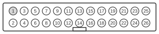 (26 Pin MALE connector on the mainboard)
| Pin No (D-Type 25) | Pin No (Centronics) | SPP Signal | Direction In/out | Register | Hardware Inverted |
|---|---|---|---|---|---|
| 1 | 1 | nStrobe | In/Out | Control | Yes |
| 2 | 2 | Data 0 | Out | Data | |
| 3 | 3 | Data 1 | Out | Data | |
| 4 | 4 | Data 2 | Out | Data | |
| 5 | 5 | Data 3 | Out | Data | |
| 6 | 6 | Data 4 | Out | Data | |
| 7 | 7 | Data 5 | Out | Data | |
| 8 | 8 | Data 6 | Out | Data | |
| 9 | 9 | Data 7 | Out | Data | |
| 10 | 10 | nAck | In | Status | |
| 11 | 11 | Busy | In | Status | Yes |
| 12 | 12 | Paper-Out / Paper-End | In | Status | |
| 13 | 13 | Select | In | Status | |
| 14 | 14 | nAuto-Linefeed | In/Out | Control | Yes |
| 15 | 32 | nError / nFault | In | Status | |
| 16 | 31 | nInitialize | In/Out | Control | |
| 17 | 36 | nSelect-Printer / nSelect-In | In/Out | Control | Yes |
| 18 - 25 | 19-30 | Ground | Gnd |
Note: Direction is Computer relative Device. The above table uses “n” in front of the signal name to denote that the signal is active low. e.g. nError. If the printer has occurred an error then this line is low. This line normally is high, should the printer be functioning correctly. The “Hardware Inverted” means the signal is inverted by the Parallel card’s hardware. Such an example is the Busy line. If +5v (Logic 1) was applied to this pin and the status register read, it would return back a 0 in Bit 7 of the Status Register. The output of the Parallel Port is normally TTL logic levels. The voltage levels are the easy part. The current you can sink and source varies from port to port. Most Parallel Ports implemented in ASIC, can sink and source around 12mA. However these are just some of the figures taken from Data sheets, Sink/Source 6mA, Source 12mA/Sink 20mA, Sink 16mA/Source 4mA, Sink/Source 12mA. As you can see they vary quite a bit. The best bet is to use a buffer, so the least current is drawn from the Parallel Port.
Signal Descriptions:
- Strobe: The strobe line is the heart of the parallel port, it tells the printer when to sample the information of the data lines, it is usually high and goes low when a byte of data is transmitted. The timing is critical for the data to be read correctly, all bits on the data lines must be present before the strobe line goes low, to insure data integrity when the printer samples the data lines. The time needed for each byte is about half a microsecond then the the strobe line goes low for about one microsecond and then the data is usually still present for another half microsecond after the strobe goes high. So the total time needed to transmit a full byte is around two microseconds.
- Data: These 8 lines carry the information to be printed and also special printer codes to set the printer in different modes like italics, each line carries a bit of information to be sent, the information here travels only from the computer to the printer or other parallel device. These lines function with standard TTL voltages, 5 volts for a logical 1 and 0 volts for a logical 0.
- Acknowledge: This line is used for positive flow control, it lets the computer know that the character was successfully received and that it’s been dealt with. It’s normally high and goes low when it has received the character and is ready for the next one, this signal stays low for about 8 microseconds.
- Busy: As seen above (strobe line), each byte takes about 2 microseconds to be sent to the printer, this means the printer is receiving about 500,000 bytes per second (1 sec divided by 2 microseconds), no printer can print this fast, so they came up with a busy line. Each time the printer receives a byte this line will send this line high to tell the computer to stop sending, when the printer is done manipulating the byte (printing, putting it in the buffer or setting it’s internal functions) it then goes back low, to let the computer know that it can send the next byte.
- Paper End: Also refered to as Paper Empty, this line will go high when you run out of paper, just like the paper out light on your printer, this way the computer will know and can tell you of the problem. When this happens the busy line will also go high so the computer stops sending data. Without this line when you would run out of paper the busy line would go high and the computer would seem to be hanged.
- Select: This line tells the computer when it is selected (or online), just like the light on your printer. When the select line is high the printer is online and is ready to receive data, when it’s low the computer will not send data.
- Auto Feed: Not all printers treat the cariage return the same way, some will just bring the print head to the begining of the the line beeing printed and some will also advance the paper one line down (or roll the paper one line up). Most printers have a DIP switch or some other way to tell your preference of how to interpret the cariage return. The auto feed signal lets your computer do the job for you, when it put’s this signal low, the printer will feed one line when it gets a cariage return, by holding the signal high the software must send a line feed along with the cariage return to obtain the same effect.
- Error: This is a general error line, there is no way of knowing the exact error from this line. When no errors are detected, this line is high, when an error is detected it goes low. Some of the errors that can arrise through this line are: cover open, print head jammed, a broken bealt by detecting that the head does not come back to it’s home position or any other error that your printer can detect.
- Initialize Printer:
- : This line is used to reinitialize the printer, the computer will accomplish this by putting the line, wich is normally high, to it’s low state. This is very useful when starting a print job, since special formating codes might have been sent to the printer on the last job, by reinitializing the printer you are sure of not messing up the whole thing, like printing the whole document in italics or something.
- Select Input: Many computers give the option of letting the computer the option of putting the printer online or not, by putting this signal high the printer is kept in it’s offline state and putting it low the printer is online and will accept data from the computer. Many printers have a DIP switch to let decide if the computer can control the online state, when the switch is active it will keep this line always low, thus keeping the computer from putting the printer offline.
- Ground: This is a regular signal ground and is used as a reference for the low signal or logical 0.
References
- IEEE 1284-1994 — Standard Signaling Method for a Bidirectional Parallel Peripheral Interface for Personal Computers — the standard that defines the port, its five modes and three connector types (A/B/C).
- IEEE 1284 — Updating the PC Parallel Port (National Instruments Application Note 062, 1995) — full SPP/EPP/ECP signal descriptions, register map and the DB-25 / Centronics / Type-C pinouts.
- Craig Peacock, Interfacing the Standard Parallel Port — parallel-port register map and signal timing reference.