
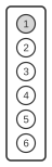
 Pin connector as seen from back of unit
This page documents the 6-pin proprietary connector found on Garmin GPS receivers. The layout provides power input, ground, an alarm signal, bidirectional serial data lines, and one unused pin. Only the six pins listed below are covered.
| Pin | Name | cable color |
|---|---|---|
| 1 | power input | red |
| 2 | ground | black |
| 3 | alarm | blue |
| 4 | data out | brown |
| 5 | data in | white |
| 6 | not used | red/black |
Notes
Pin numbers refer to the connector on the device as seen from the back of the unit; pins not listed are unused.
References
- Garmin GPS to PC Wiring Instructions (P/N 190-00222-00) — Garmin Corporation; “units with 6 pin plug”.