
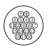
 Pin connector as seen from back of unit
The 18-pin connector is the proprietary data and power interface used on certain Garmin GPS receivers. Active signals — power input, serial data in and out, alarm, and ground — are concentrated at the higher-numbered pins, while pins 1–10 and 12–14 are unused in the documented wiring. Only the pins listed below are defined for this connector.
| Pin | Name | cable color |
|---|---|---|
| 1 | not used | |
| 2 | not used | |
| 3 | not used | |
| 4 | not used | |
| 5 | not used | |
| 6 | not used | |
| 7 | not used | |
| 8 | not used | |
| 9 | not used | |
| 10 | not used | |
| 11 | alarm | yellow |
| 12 | not used | |
| 13 | not used | |
| 14 | not used | |
| 15 | power input | red |
| 16 | data in | brown |
| 17 | data out | blue |
| 18 | ground | black |
Notes
Pin numbers refer to the connector on the device as seen from the back of the unit; pins not listed as active are unused.
References
- Garmin GPS to PC Wiring Instructions (P/N 190-00222-00) — Garmin Corporation; “units with 18 pin plug”.