
A USB-to-PS/2 mouse adapter is a passive wiring adapter — it contains no active circuitry. It functions only with dual-protocol mice that detect at power-on which interface they are connected to and switch accordingly; the intelligence resides entirely in the mouse firmware. The USB Type A connector carries VBUS (+5V), D−, D+, and GND on pins 1–4, whilst the PS/2 side uses a 6-pin mini-DIN connector in which pin 1 = Data, pin 3 = GND, pin 4 = +5V, and pin 5 = CLK, as defined by IBM with the Personal System/2 family in 1987. The adapter simply maps USB D− to PS/2 Data and USB D+ to PS/2 CLK; a mouse that does not support both USB HID and PS/2 protocols will not operate through such an adapter.
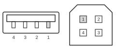 4 pin USB A or USB B plug connector to the mouse
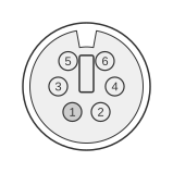 6 pin mini-DIN male (PS/2 STYLE) connector to the PS/2 mouse cable
| mouse Name | mouse Pin | Direction | PS/2 mouse conteroller Pin | PS/2 mouse conteroller Name | Description |
|---|---|---|---|---|---|
| VDC +5V | 1 | ← | 4 | VDC +5V | |
| Data- | 2 | 1 | Data | ||
| Data+ | 3 | 5 | Clock | ||
| Ground | 4 | 3 | Ground |
Notes
- The adapter is passive; it contains no circuitry and performs no protocol conversion.
- Only mice that natively support both USB HID and PS/2 protocols will operate through this adapter. The mouse detects the interface at power-on by sensing the pin voltages present (USB D+/D− vs PS/2 clock/data lines).
- The PS/2 port supplies +5V on mini-DIN pin 4; the USB VBUS (+5V) on pin 1 maps directly to this supply.
- PS/2 clock and data lines are open-collector, TTL-level (0 V / +5 V); clock frequency 10–16.7 kHz; 11-bit frames (start, 8 data bits LSB-first, odd parity, stop).
- Many retail dual-protocol mice (for example the Microsoft IntelliMouse Optical) shipped with a passive PS/2 adapter included in the packaging.
Signals
USB side (Type A plug, pins 1–4)
- VBUS — +5 V supply from host; maps to PS/2 VCC
- D− — USB differential data (negative); maps to PS/2 Data
- D+ — USB differential data (positive); maps to PS/2 Clock
- GND — Signal and power ground; maps to PS/2 GND
PS/2 side (6-pin mini-DIN male)
- Data (pin 1) — Bidirectional synchronous serial data; open-collector, TTL level
- NC (pin 2) — Not connected
- GND (pin 3) — Signal and power ground
- VCC (pin 4) — +5 V supply to mouse
- CLK (pin 5) — Bidirectional clock; open-collector, TTL level; 10–16.7 kHz
- NC (pin 6) — Not connected
References
- IBM PS/2 Hardware Interface Technical Reference: Common Interfaces (October 1990, Part No. 84F9735)
- IBM Personal System/2 Hardware Interface Technical Reference (May 1988)
- Microsoft IntelliMouse Optical 1.1a Technical Data Sheet
- Device Class Definition for Human Interface Devices (HID), Version 1.11 — USB Implementers Forum, 27 June 2001