
 9 pin D-SUB female connector to the computer serial port
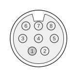 8 pin mini-DIN male connector to the mouse
The Kensington Expert Mouse trackball in its serial variant connects to a host PC via a proprietary 8-pin mini-DIN connector on the device side, terminating in a DE-9 female connector that plugs into a standard RS-232 serial port. The device operates as a Microsoft-compatible serial mouse at 1200 baud, 7 data bits, transmitting 3-byte movement packets; the host detects the device by toggling DTR and RTS and awaiting an identification byte. Kensington has not published a public specification for this cable’s pinout.
| computer serial port Name | computer serial port Pin | Direction | mouse Pin | mouse Name | Description |
|---|---|---|---|---|---|
| CD | 1 | ← | 5 | CD | Carrier Detect |
| RXD | 2 | ← | 4 | RXD | Receive Data |
| TXD | 3 | → | 7 | TXD | Transmit Data |
| DTR | 4 | → | 6 | DTR | Data Terminal Ready |
| GND | 5 | — | 2 | GND | Ground |
| DSR | 6 | → | 1 | DSR | Data Set Ready |
| RTS | 7 | ← | 3 | RTS | Request to send |
| CTS | 8 | ← | 8 | CTS | Clear to Send |
Signals
- CD — Carrier Detect; RS-232 modem-control line carried through the cable.
- RXD — Receive Data; carries serial data from the trackball to the host at 1200 baud.
- TXD — Transmit Data; carries data from the host to the trackball.
- DTR — Data Terminal Ready; toggled by the host during device detection and used as part of the power/handshake sequence.
- GND — Signal Ground; common reference for all RS-232 signals.
- DSR — Data Set Ready; modem-control line wired through the cable.
- RTS — Request to Send; toggled with DTR during host detection sequence; also supplies power to the device’s on-board voltage conversion circuit.
- CTS — Clear to Send; modem-control line wired through the cable.
Notes
- Pin 9 on the DE-9 connector is not connected.
- The serial mouse detection sequence requires the host to de-assert both DTR and RTS for at least 100 ms, then assert DTR followed by RTS; the device responds with the identification byte 0x4D (‘M’) within approximately 10–20 ms.
- The trackball draws operating power from the RTS line via an on-board voltage conversion circuit; maximum current draw from the RS-232 port is 10 mA.
- Movement data is transmitted as 3-byte packets: byte 1 contains the sync bit, button state, and upper X/Y displacement bits; bytes 2 and 3 carry the lower X and Y displacement values respectively.
- The 8-pin mini-DIN connector on the device is proprietary to this cable assembly and is not interchangeable with PS/2 or other standard mini-DIN peripherals.